
16 LED Chaser

The circuit described is a double-direction LED flash system that utilizes several integrated circuits (ICs) and discrete components to create a visually dynamic lighting effect. The primary function of this circuit is to control the sequential illumination of a series of LEDs, creating an up-and-down motion effect that can switch direction based on specific conditions.
The heart of the circuit is IC1, a 555 timer configured as an astable multivibrator. This configuration allows it to generate a continuous square wave output, which serves as a clock signal for the subsequent components. The frequency of this oscillation can be adjusted using the variable resistor TR1, which alters the timing of the charge and discharge cycles of the timing capacitor C1 (330nF). The result is a change in the speed at which the LEDs illuminate, allowing for customizable visual effects.
The output from the 555 timer feeds into IC2, which consists of NAND gates that form a flip-flop configuration. This flip-flop is crucial for determining the state change of the LED sequence. When the LEDs at positions D1 and D16 are activated, the flip-flop changes state, triggering the counter IC3 (74193), a 4-bit up/down counter. The counter keeps track of the current position of the lit LED and alters the output accordingly to create the desired up-and-down motion.
The output from the counter is directed to IC4 (74154), a decoder that drives the individual LEDs (D1 to D16). Depending on the output from the counter, a specific LED is illuminated, creating the visual effect of a moving dot. When the last LED (D16) is lit, the system reverses the direction of the sequence, causing the lit dot to move back down the line of LEDs. The configuration of the circuit allows for a variety of patterns and effects, depending on the timing and state of the flip-flop and counter.
The component list includes resistors R1 (100kΩ), R2 (220kΩ), and R3 (470Ω), which serve to limit current and set the operating parameters for the ICs. The use of 5mm LEDs (D1 to D16) provides the visual output, while the ICs (555 timer, 7400 NAND gates, 74193 counter, and 74154 decoder) form the logical backbone of the circuit, enabling the desired functionality. This circuit exemplifies a creative use of basic electronic components to achieve complex visual effects through sequential LED illumination.This circuit is a double direction flash. Similar to Digital Ping- Pong 1, there is a movement of a lit dot, up and down along the LED's length. When the D16 lit the situation changes and there is a reverse movement. Lit D15-14 ??D16, is lit making circles when the circuit is under power. The IC1 is an unstable flip- flop supplying with stable frequency pulses (the frequency can be changed by TR1, adjusting the velocity of the LED's up and down).
This frequency supplies the IC3 (which is a 4-Bit UP and DOWN counter) through 2 gates A-B of the IC2. The output counter supplies the IC4 that is the driver of the LED's. The parts C- D of The IC2, make a R-S flip- flop, that changes situation, when the edge LED's D1 and D16 lit. We have an electronic limit for the situation change. In proportion the shape we make with the LED's, we can have the proportionate optional result, making various effects.
Part List R1= 100Kohms C1= 330nF 100V MKT IC3= 74193 R2= 220Kohms D1-16= LED 5mm IC4= 74154 R3= 470 ohms IC1= 555 TR1= 1Mohms IC2= 7400 🔗 External reference
Related Circuits

This is a capacitor power supply. This is a very small current of energy-effective because it has very little loss, much smaller than the miniature transformer. Capacitor impedance is inversely proportional to frequency. This is a great disadvantage when...
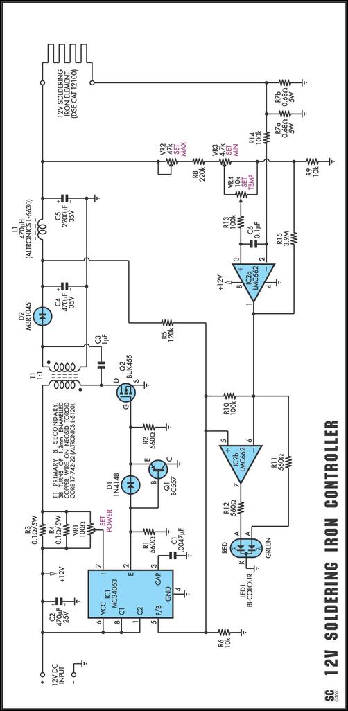
One reason commercial soldering stations are costly is that they typically use soldering irons equipped with built-in temperature sensors, like thermocouples. This circuit design eliminates the necessity for a specialized sensor by directly sensing the temperature of a soldering...

Some simple 555 and flip-flop circuits are being developed to add electronic lighting effects to modernize games. Various circuits are being collected for different game aspects, such as idle states, flipper shots, flower openings, winning shots, etc. A collection...

In various industrial processes, it is essential to rotate a DC (or AC) motor both forward and reverse for a specified duration. Initially, the motor rotates forward (clockwise) for a certain period (approximately 2 to 3 minutes), then stops...

This circuit operates 25 LEDs powered by a mains supply of 230V. A fluorescent lamp adapter was acquired from a scrap dealer for ease of disassembly. The circuit consists of a series of 25 light-emitting diodes (LEDs) arranged to operate...

Conventionally, a MOSFET with a voltage rating of 1500V or a Half-Bridge configuration utilizing two MOSFETs rated at 800-900V is employed for Switch Mode Power Supply (SMPS) applications that require input voltages exceeding 380Vac. However, these methods present challenges,...