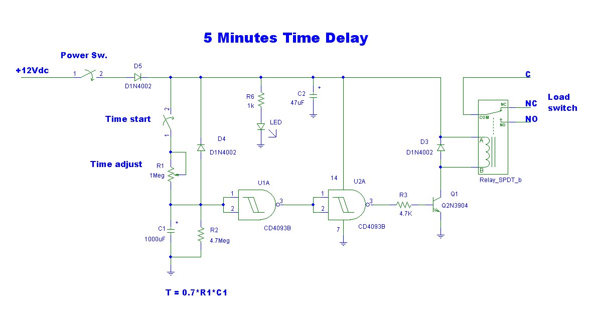
5 Minutes Time Delay using CD4093

This is a simple delay timer circuit model designed to control the timing of electrical appliances. It provides a delay of approximately 5 minutes before turning off the connected devices.
The delay timer circuit functions by utilizing a timing mechanism that can be implemented with various components such as resistors, capacitors, and a relay. The primary components typically include a resistor-capacitor (RC) network that determines the delay time, a transistor or operational amplifier for switching, and a relay to control the power to the appliances.
When power is applied to the circuit, the capacitor begins to charge through the resistor. The time it takes for the capacitor to charge to a certain voltage level is directly proportional to the resistance and capacitance values used in the circuit, following the formula \( t = R \times C \). Once the capacitor reaches the predetermined voltage, it activates the transistor, which in turn energizes the relay. This action closes the circuit and allows current to flow to the connected appliances.
After the set time of approximately 5 minutes elapses, the capacitor discharges, causing the transistor to turn off, which deactivates the relay and cuts power to the appliances. This circuit can be adjusted for different delay times by changing the resistor and capacitor values, making it versatile for various applications where a timed delay is required.
For practical implementation, it is essential to ensure that the relay used can handle the load of the connected appliances and that all components are rated for the appropriate voltage and current levels. Additionally, incorporating a diode across the relay coil can help protect the circuit from back EMF generated when the relay is deactivated.This be delay timer circuit model to be simple. It be the character delays to close electric all appliances. By fix the time about 5 minute. It can fine.. 🔗 External reference


