Product Defect Classification in Manufacturing
1. Key Concepts in Defect Classification
1.1 Key Concepts in Defect Classification
Defect Taxonomy and Feature Extraction
Defect classification begins with a rigorous taxonomy that categorizes anomalies based on their physical characteristics, root causes, and impact on product functionality. Common defect types include geometric deformations (e.g., warping, misalignment), surface irregularities (e.g., scratches, pits), and material inconsistencies (e.g., voids, inclusions). Feature extraction transforms raw sensor data (e.g., images, spectral readings) into discriminative representations. For visual inspection, convolutional neural networks (CNNs) automatically learn hierarchical features, while engineered features like Haralick textures or Zernike moments provide interpretability.
Mathematical Foundations of Classification
Given a feature vector x ∈ ℝd, defect classification assigns a label y ∈ {1, ..., K} via a decision function f(x). For probabilistic models like Gaussian Mixture Models (GMMs), the class posterior is computed as:
where πk are mixing coefficients and μk, Σk are the mean and covariance of the k-th component. Deep learning approaches replace this with trainable nonlinear transformations fθ(x) optimized via cross-entropy loss:
Imbalanced Data Handling
Manufacturing datasets often exhibit extreme class imbalance (e.g., 99% non-defective samples). Techniques to address this include:
- Synthetic Minority Oversampling (SMOTE): Generates synthetic defect samples via convex combinations of nearest neighbors.
- Focal Loss: Rescales cross-entropy to focus on hard misclassified examples:
$$ FL(p_t) = -\alpha_t (1 - p_t)^\gamma \log(p_t) $$
- Cost-sensitive Learning: Assigns higher penalties to misclassifying rare defect classes during model training.
Multimodal Sensor Fusion
High-accuracy systems integrate data from multiple sensors (e.g., RGB cameras, thermal imagers, vibration sensors). Early fusion concatenates raw features, while late fusion combines decision-level outputs. A hybrid approach uses attention mechanisms to dynamically weight modalities:
where hm are modality-specific embeddings and q, W, b are learnable parameters.
Real-Time Constraints
Production lines require inference latencies under 100ms. Optimizations include:
- Model Distillation: Trains compact student networks to mimic larger teacher models.
- Quantization: Reduces precision from 32-bit floats to 8-bit integers with minimal accuracy loss.
- Edge Deployment: Executes models on FPGA or ASIC hardware for deterministic timing.
Uncertainty Estimation
Bayesian neural networks or Monte Carlo dropout provide confidence estimates critical for risk management:
where T stochastic forward passes generate predictions {ŷ1, ..., ŷT}.

1.2 Types of Manufacturing Defects
Geometric Defects
Geometric defects arise from deviations in the intended shape, dimensions, or surface topology of a manufactured part. These include warping, shrinkage, and dimensional inaccuracies caused by thermal stresses, improper tooling, or material inhomogeneity. In additive manufacturing, layer misalignment or uneven cooling rates introduce geometric distortions. For a part with intended dimensions (L, W, H), the deviation Δ can be quantified using the root mean square error (RMSE):
where xi is the measured dimension and ĝi is the nominal value. Tolerances beyond ±2σ of the RMSE typically classify the part as defective.
Material Defects
Material defects stem from impurities, voids, or microstructural anomalies. Common types include:
- Inclusions: Foreign particles embedded during casting or forging, reducing fatigue life.
- Porosity: Gas entrapment or insufficient compaction, modeled by the void volume fraction fv:
Critical thresholds for fv depend on the material; for aerospace-grade aluminum, fv > 0.1% often necessitates rejection.
Surface Defects
Surface anomalies such as scratches, pits, or oxidation layers compromise functional performance. Roughness parameters like Ra (arithmetic mean deviation) or Rz (maximum height) are used for quantification. Electroplating defects, for instance, exhibit Ra values exceeding 1.6 µm due to uneven deposition rates.
Assembly Defects
Misalignment, fastener failures, or incorrect component placement during assembly lead to functional failures. Statistical process control (SPC) charts monitor critical parameters like torque values or gap widths. For a bolted joint, the clamping force F must satisfy:
where d is the bolt diameter, σy is the yield strength, and k is the safety factor.
Functional Defects
These defects manifest during operation, such as electrical shorts in PCBs or bearing wear. Accelerated life testing (ALT) models failure rates using the Arrhenius equation for thermally activated failures:
where MTTF is mean time to failure, Ea is activation energy, and T is absolute temperature.
Importance of Defect Classification in Quality Control
Defect classification serves as the backbone of modern quality control systems in manufacturing, enabling precise identification, quantification, and mitigation of production anomalies. Its significance extends beyond mere detection—it provides actionable insights into root causes, process inefficiencies, and material inconsistencies. Advanced defect classification systems leverage machine learning to categorize defects with sub-pixel accuracy, often achieving discrimination thresholds below 0.1mm for critical components.
Statistical Process Control Integration
When integrated with Statistical Process Control (SPC), defect classification transforms raw anomaly data into quantifiable process metrics. Consider a production line with a baseline defect rate λ following a Poisson distribution:
where k represents defect counts. Classification enables separation of defect modes, allowing multivariate SPC charts to track distinct failure mechanisms. For instance, a semiconductor fab might simultaneously monitor:
- Particle contamination (Poisson-distributed)
- Edge chipping (Weibull-distributed)
- Layer misalignment (Gaussian-distributed)
Cost Optimization Through Defect Severity Analysis
Advanced classification systems employ cost matrices that weight defects by their impact on product performance. A typical aerospace component might use:
where Si is severity score (1-10), Fi is failure probability, and Ri is repair cost. This enables Pareto-based resource allocation, with industrial case studies showing 30-45% reduction in quality costs when implementing ML-driven classification versus manual inspection.
Material Science Applications
In additive manufacturing, defect classification correlates microstructure anomalies with process parameters. Electron microscopy reveals that lack-of-fusion defects follow distinct spatial patterns compared to gas porosity:
- Lack-of-fusion: Elongated voids aligned with scan direction
- Gas porosity: Spherical voids with random distribution
Convolutional neural networks trained on these morphologies achieve >98% classification accuracy in titanium alloys, enabling real-time laser power adjustment during printing.
Regulatory Compliance and Traceability
Modern quality standards like IATF 16949 require defect classification systems to maintain traceability across supply chains. A blockchain-integrated classification system might record:
where H is the cryptographic hash, Dt is defect data, and Tt is timestamp. This creates an immutable record of defect evolution across production batches.
2. Sensor and Imaging Technologies for Defect Detection
2.1 Sensor and Imaging Technologies for Defect Detection
Optical Imaging and Hyperspectral Analysis
High-resolution optical imaging remains a cornerstone of defect detection, particularly for surface anomalies such as scratches, cracks, or misalignments. Modern systems employ hyperspectral imaging, which captures data across hundreds of narrow spectral bands, enabling material characterization beyond visible light. The spectral signature S(λ) of a defective region often deviates from the nominal material response, allowing classification via spectral angle mapper (SAM) algorithms:
where S1 and S2 are the spectral vectors of the test pixel and reference material, respectively. Industrial implementations achieve sub-millimeter resolution with line-scan cameras operating at >1 kHz frame rates.
X-ray Computed Tomography (CT)
For internal defects like voids or inclusions, X-ray CT provides non-destructive 3D volumetric reconstruction. The attenuation coefficient μ(x,y,z) is reconstructed from projections using filtered backprojection:
where Pθ(t) is the projection at angle θ, and h(t) is the Ram-Lak filter. Modern micro-CT systems achieve <5 μm voxel resolution, critical for aerospace component inspection. Phase-contrast CT further enhances sensitivity to low-density defects by exploiting refractive index variations.
Thermographic Inspection
Active thermography detects subsurface defects through thermal diffusivity variations. A pulsed heat source (laser/flash lamp) excites the surface, with defect locations appearing as temperature anomalies in the time-domain response:
where Q is absorbed energy, e is material effusivity, α is thermal diffusivity, and d is defect depth. Lock-in thermography improves SNR by modulating the heat source at specific frequencies (typically 0.01–10 Hz) and measuring phase shifts in the thermal wave.
Ultrasonic and Eddy Current Testing
High-frequency ultrasound (>10 MHz) provides depth-resolved defect mapping through time-of-flight analysis of reflected waves. The acoustic impedance mismatch Z at defect boundaries causes partial reflection:
Eddy current testing excels for conductive materials, where defects perturb induced current flow. The complex impedance Z of the probe coil varies with defect presence:
where k is the coupling coefficient and τ is the material's time constant. Multi-frequency eddy current systems separate surface from subsurface defects through skin depth effects.
Multisensor Data Fusion
Advanced systems combine modalities through Bayesian inference or deep learning architectures. A convolutional neural network (CNN) may process heterogeneous inputs as:
where X is the stacked sensor data tensor. Industrial implementations demonstrate 15–30% higher F1-scores compared to single-modality systems, particularly for complex defects like stress corrosion cracking.

2.2 Data Annotation and Labeling Strategies
Hierarchical Labeling for Multi-Scale Defects
Manufacturing defects often exhibit hierarchical structures where coarse-grained categories (e.g., "surface defects") contain fine-grained subcategories (e.g., "scratches", "pits", "cracks"). A multi-level labeling scheme improves model performance by capturing these relationships. The hierarchical cross-entropy loss function extends standard classification:
where L represents hierarchy levels, Cl denotes classes at level l, and wl are level-specific weights. This formulation enables knowledge transfer between related defect types while maintaining granular classification.
Uncertainty-Aware Annotation Protocols
For ambiguous defect cases, standard binary labeling (defective/non-defective) introduces noise. Probabilistic labeling better captures expert uncertainty:
- Fuzzy labeling: Annotators assign confidence scores [0,1] for each class
- Multi-expert consensus: Aggregate labels from ≥3 domain experts
- Boundary case flagging: Mark borderline defects for special handling
The resulting probabilistic labels train models to estimate prediction confidence, crucial for safety-critical applications. The annotation uncertainty U can be quantified using Shannon entropy:
Active Learning for Annotation Efficiency
Strategic sample selection reduces labeling costs while maximizing model improvement. The most informative samples for annotation are identified by:
where U is the unlabeled pool, and the terms represent uncertainty (Monte Carlo dropout variance), decision boundary proximity (margin), and feature space coverage. In automotive manufacturing case studies, this approach reduced required annotations by 62% while maintaining 98% of full-dataset performance.
Temporal Consistency in Video Annotation
For conveyor belt inspection systems, frame-by-frame labeling creates temporal inconsistencies. Spatiotemporal annotation methods include:
- Track-and-propagate: Annotate keyframes with defect tracking between frames
- 3D segmentation: Label defects in volumetric reconstructions
- Motion-guided interpolation: Use optical flow to propagate labels
The temporal smoothness loss during training regularizes model predictions:
Domain-Adaptive Label Transfer
When introducing new manufacturing lines, label transfer from existing systems reduces annotation costs. Feature space alignment using Maximum Mean Discrepancy (MMD) enables cross-domain knowledge transfer:
where ϕ maps to reproducing kernel Hilbert space H. Combined with pseudo-labeling, this approach achieved 89% accuracy on new production lines using only 10% new annotations in semiconductor wafer inspection systems.
2.3 Feature Extraction and Dimensionality Reduction
Feature Extraction from Manufacturing Data
Raw manufacturing data from sensors, vision systems, and production logs contains high-dimensional information that often includes redundant or irrelevant features. Effective feature extraction transforms this data into a lower-dimensional representation while preserving discriminative information for defect classification. For visual inspection systems, convolutional neural networks (CNNs) automatically learn hierarchical features through successive layers:
where fl(x) represents features at layer l, Wl denotes learnable filters, bl is the bias term, and σ is the activation function. For time-series sensor data, spectral features like Mel-frequency cepstral coefficients (MFCCs) or statistical moments provide compact representations.
Dimensionality Reduction Techniques
Principal Component Analysis (PCA) remains a fundamental linear technique for manufacturing applications. Given a centered dataset X ∈ ℝn×d, PCA computes eigenvectors of the covariance matrix:
where V contains principal components and Λ is a diagonal matrix of eigenvalues. For nonlinear manifolds common in manufacturing defects, t-distributed Stochastic Neighbor Embedding (t-SNE) preserves local structures:
Feature Selection for Defect Classification
Mutual information-based feature selection evaluates the dependency between features X and defect classes Y:
Recursive feature elimination with cross-validation (RFECV) systematically removes the least important features based on classifier performance. In semiconductor manufacturing, this approach reduces feature dimensions by 60-80% while maintaining >95% classification accuracy.
Deep Feature Extraction Architectures
Autoencoder networks learn compressed representations through a bottleneck architecture:
where fϕ is the encoder and gθ is the decoder. Variational autoencoders (VAEs) introduce probabilistic latent spaces:
In automotive part inspection, these techniques reduce input dimensions from 10,000+ raw pixels to <200 latent features with minimal information loss.
Practical Implementation Considerations
Feature extraction pipelines must address manufacturing-specific challenges:
- Real-time constraints: PCA and linear discriminant analysis (LDA) execute in O(d2n) time for d features and n samples
- Non-stationary distributions: Online PCA adapts to drifting feature spaces in continuous production
- Multimodal data fusion: Graph neural networks combine visual, spectral, and geometric features

3. Supervised Learning Models (CNNs, SVMs, Random Forests)
3.1 Supervised Learning Models (CNNs, SVMs, Random Forests)
Convolutional Neural Networks (CNNs) for Visual Defect Detection
CNNs excel at processing high-dimensional image data, making them ideal for visual inspection tasks in manufacturing. The hierarchical feature extraction in CNNs occurs through successive convolutional layers that apply learned filters to detect increasingly complex patterns. For a defect classification task, the network architecture typically includes:
- Input layer normalized to pixel intensity ranges (0-255)
- Multiple convolutional blocks with ReLU activation: $$ f(x) = max(0,x) $$
- Pooling layers (max or average) for spatial invariance
- Final dense layers with softmax for multi-class output: $$ \sigma(z)_i = \frac{e^{z_i}}{\sum_{j=1}^K e^{z_j}} $$
In industrial applications, architectures like ResNet-50 or EfficientNet are often fine-tuned on defect datasets. The training objective minimizes categorical cross-entropy loss:
Support Vector Machines (SVMs) for High-Dimensional Separation
SVMs construct optimal hyperplanes in feature space to separate defect classes. For non-linear separation, kernel methods project data into higher dimensions:
The optimization problem maximizes the margin while minimizing classification error:
For manufacturing applications, SVMs perform well on engineered features like Haralick textures or Fourier descriptors extracted from defect regions.
Random Forests for Heterogeneous Feature Spaces
Random Forests aggregate predictions from multiple decision trees, each trained on bootstrap samples and random feature subsets. The Gini impurity criterion guides node splitting:
Key advantages for defect classification include:
- Native handling of mixed data types (images, sensor readings, categorical variables)
- Built-in feature importance ranking
- Robustness to outliers through ensemble averaging
Model Selection Considerations
The choice between these models depends on several factors:
| Model | Data Requirements | Training Time | Interpretability |
|---|---|---|---|
| CNNs | Large labeled image sets | High (GPU preferred) | Low (black box) |
| SVMs | Feature-engineered data | Medium | Medium (kernel-dependent) |
| Random Forests | Tabular or mixed data | Low | High (feature importance) |
In practice, hybrid approaches often yield best results - using CNNs for initial feature extraction from images, then feeding these features into ensemble classifiers for final decision making.

3.2 Unsupervised and Semi-Supervised Techniques
Traditional supervised learning approaches for defect classification require large labeled datasets, which are often expensive and time-consuming to acquire in manufacturing settings. Unsupervised and semi-supervised techniques address this challenge by leveraging unlabeled data, which is typically abundant in production environments.
Clustering-Based Defect Detection
Unsupervised clustering algorithms automatically group similar instances without prior knowledge of defect categories. For high-dimensional manufacturing data (e.g., spectral measurements or high-resolution images), dimensionality reduction is often applied first:
where xi represents raw sensor data and fθ is a nonlinear projection to a lower-dimensional space d. Common approaches include:
- k-means clustering: Minimizes within-cluster variance:
$$ \min_{C} \sum_{k=1}^K \sum_{x \in C_k} \|x - \mu_k\|^2 $$
- Gaussian Mixture Models (GMM): Fits multivariate normal distributions to capture complex defect patterns
- DBSCAN: Density-based clustering effective for detecting rare anomalies
Semi-Supervised Learning Frameworks
When limited labeled data is available, semi-supervised approaches combine supervised and unsupervised learning. The general objective function combines labeled and unlabeled losses:
Key methods include:
Consistency Regularization
Enforces model predictions to be invariant to small perturbations of the input, particularly effective for image-based defect detection:
Graph-Based Methods
Constructs a similarity graph where nodes represent labeled and unlabeled samples, and edges encode feature similarities. The label propagation objective:
where L is the graph Laplacian and Y contains known labels.
Deep Generative Models
Variational Autoencoders (VAEs) and Generative Adversarial Networks (GANs) learn the data distribution of normal products, enabling defect detection as outliers:
Industrial case studies show VAEs achieve >90% precision in detecting subtle material defects when trained on only 100 labeled examples combined with 50,000 unlabeled samples.
Self-Supervised Pretraining
Leverages pretext tasks (e.g., predicting rotation angles or solving jigsaw puzzles) to learn transferable representations from unlabeled data. The pretrained model is then fine-tuned on limited defect labels:
Recent work shows that contrastive learning (e.g., SimCLR) outperforms traditional pretraining for surface defect classification, reducing required labeled data by 10× while maintaining 98% accuracy.

3.3 Deep Learning Architectures for High-Accuracy Classification
Convolutional Neural Networks (CNNs) for Visual Defect Detection
CNNs remain the dominant architecture for visual defect classification due to their hierarchical feature extraction capabilities. The core operation is the convolution between input tensor X and learnable kernel W:
Modern implementations employ depthwise separable convolutions to reduce computational complexity while maintaining accuracy. For a defect classification task with N classes, the final layer typically uses softmax activation:
Attention Mechanisms and Transformer-Based Models
Vision Transformers (ViTs) have demonstrated superior performance in cases requiring global context understanding. The multi-head attention mechanism computes:
where Q, K, and V represent queries, keys, and values respectively. Hybrid architectures combining CNNs with attention blocks achieve 98.7% accuracy on PCB defect datasets.
Residual Networks and Skip Connections
Deep networks with residual blocks mitigate vanishing gradients through identity mappings:
Recent variants like ResNeXt-101 (32×4d) demonstrate particular effectiveness for multi-scale defect recognition, with 3.2% lower false positive rates compared to standard ResNet architectures.
Efficient Architectures for Edge Deployment
MobileNetV3 and EfficientNet architectures optimize the accuracy-latency tradeoff through:
- Inverted residual blocks with linear bottlenecks
- Neural architecture search-derived scaling coefficients
- Squeeze-and-excitation attention gates
The compound scaling method uniformly adjusts network depth, width, and resolution:
Multimodal Fusion Architectures
For systems combining visual, thermal, and vibration data, late fusion architectures concatenate modality-specific features:
Graph neural networks have shown promise when defect relationships must be modeled as non-Euclidean manifolds, particularly for composite material inspection.

4. Integration with Production Lines
Integration with Production Lines
Real-time defect classification in manufacturing requires seamless integration with production line systems, including programmable logic controllers (PLCs), industrial IoT (IIoT) sensors, and manufacturing execution systems (MES). The primary challenge lies in achieving low-latency inference while maintaining high accuracy, often necessitating edge computing deployments rather than cloud-based processing. A typical integration architecture consists of three layers:
- Data Acquisition Layer: High-speed cameras, spectral sensors, or vibration monitors capture raw product data at line speed.
- Edge Processing Layer: Embedded GPUs or FPGA-based accelerators run lightweight neural networks (e.g., MobileNetV3, EfficientNet-Lite) for defect detection.
- Control Layer: Classification results trigger PLC commands for product rejection or process adjustment via OPC UA or Modbus protocols.
Latency Budget Analysis
For integration with high-speed production lines (e.g., >1000 units/minute), the total allowable latency between image capture and rejection signal must be under 50ms. This constraint decomposes into:
Where Tcapture depends on camera shutter speed (typically 1-10ms), Ttransfer involves DMA transfers to GPU memory (~2ms), and Tdecision accounts for PLC response time (5-15ms). This leaves 20-30ms for neural network inference, requiring careful model optimization:
Where α represents the hardware utilization factor (typically 0.6-0.8 for embedded GPUs). For an NVIDIA Jetson AGX Orin (2048 CUDA cores @ 1.3GHz), this translates to a maximum of 50-60 GFLOPs per inference.
Hardware-Software Co-Design
Meeting these constraints requires co-optimization across multiple dimensions:
- Model Quantization: INT8 quantization typically provides 3-4x speedup over FP16 with <1% accuracy drop when using calibration-aware training.
- Hardware-Specific Optimizations: TensorRT leverages NVIDIA GPU tensor cores for mixed-precision matrix operations, while OpenVINO optimizes for Intel CPU/FPGA pipelines.
- Pipeline Parallelism: Overlapping data transfer with computation using CUDA streams or Direct Memory Access (DMA) engines.
Case Study: Automotive Welding Inspection
A Tier 1 automotive supplier implemented a ResNet-18 variant running on a Xilinx Zynq UltraScale+ MPSoC, achieving 98.7% defect detection accuracy at 23ms latency. Key optimizations included:
- Pruning filters with <5% L1-norm contribution
- Replacing final dense layers with depthwise separable convolutions
- Implementing region-of-interest (ROI) preprocessing to reduce input resolution from 2048×1536 to 512×512
Synchronization Challenges
Precision timing requirements demand hardware-level synchronization between vision systems and mechanical actuators. Common solutions include:
- IEEE 1588 (PTP) for sub-microsecond clock synchronization across devices
- Encoder-based triggering of image capture at exact conveyor positions
- FPGA-implemented hardware triggers for rejection mechanisms
Failure modes analysis shows that jitter >200μs in rejection timing can lead to 0.5-2% false accepts at line speeds above 3m/s, necessitating careful timing loop design with phase-locked loops (PLLs) and jitter attenuation filters.
4.2 Real-Time Defect Detection Systems
Architecture of Real-Time Systems
Real-time defect detection systems integrate high-speed imaging, computational hardware, and machine learning models to analyze products on production lines at throughput rates exceeding 1,000 units per minute. The architecture typically consists of:
- High-speed cameras (e.g., CMOS sensors with ≥1,000 fps) synchronized with production line triggers.
- Edge computing units (e.g., NVIDIA Jetson AGX Orin) for low-latency inference.
- Multi-stage neural networks combining lightweight feature extractors (e.g., MobileNetV3) with spatial attention modules for localized defect analysis.
Latency-Optimized Model Design
To meet real-time constraints, models must balance accuracy and inference speed. The computational budget is governed by:
where TPM is throughput (units/minute) and Tpreproc/postproc are image handling times. For a 1,000 TPM system with 5 ms overhead, models must infer in ≤55 ms. This is achieved via:
- Architecture pruning: Removing redundant filters while preserving accuracy through iterative magnitude-based pruning.
- Quantization: INT8 precision reduces model size 4× with <2% accuracy drop in most industrial cases.
Temporal Consistency Filters
High-speed imaging captures sequential frames of each product. Temporal consistency filters exploit this by:
where Ct is the consistency score for prediction Pt, k is the temporal window, and α is a decay factor (typically 0.8–0.95). Predictions with Ct < 0.7 are flagged for review.
Hardware-Software Co-Design
Optimal performance requires matching model operations to hardware capabilities:
- Tensor core alignment
- Memory hierarchy awareness: Tiling strategies that maximize L2 cache hits reduce DRAM access by 60%.
Case Study: Automotive Welding Inspection
A Tier-1 supplier implemented a YOLOv5 variant on 8x Jetson Xavier NX devices, achieving:
- 98.4% recall for weld spatter defects at 23 ms inference time.
- False positive rate of 0.2%, validated across 1.2 million welds.
- Dynamic load balancing across GPUs reduced peak latency variance from 12 ms to 1.8 ms.
Failure Mode Analysis
Common pitfalls in deployment include:
- Overfitting to training conditions: Models trained under ideal lighting fail when ambient IR from heaters changes.
- Hardware drift: CMOS sensor degradation increases noise, requiring quarterly recalibration.

4.3 Scalability and Performance Optimization
Distributed Training Strategies
When scaling defect classification systems to high-throughput manufacturing lines, distributed training becomes essential. The most effective approaches leverage data parallelism with synchronous stochastic gradient descent (SGD). For a cluster with N workers, the weight update rule becomes:
Where gradients are averaged across workers before each update. Modern frameworks like TensorFlow and PyTorch implement this via AllReduce operations, with Ring-AllReduce being particularly efficient for large parameter counts. Batch normalization layers must synchronize statistics across devices - a critical detail often overlooked in implementation.
Model Architecture Optimization
For real-time defect detection, the latency-accuracy tradeoff requires careful balancing. The following techniques prove most effective:
- Neural Architecture Search (NAS): Automated discovery of Pareto-optimal architectures for given hardware constraints
- Pruning: Iterative magnitude pruning achieves 80-90% sparsity with <1% accuracy drop
- Quantization: INT8 quantization reduces memory bandwidth by 4x while maintaining <0.5% mAP degradation
The optimal compression strategy depends on the defect characteristics. For subtle texture defects, pruning outperforms quantization, while for geometric defects, the reverse holds true.
Hardware-Software Co-Design
Deployment on edge devices requires matching model architectures to hardware capabilities. Key considerations include:
For NVIDIA Jetson platforms, TensorRT optimizations like layer fusion and kernel auto-tuning typically yield 3-5x speedup over vanilla ONNX models. On FPGA implementations, replacing standard convolutions with depthwise separable variants reduces DSP block usage by 60% while maintaining 98% of original accuracy.
Data Pipeline Optimization
The data loading pipeline often becomes the bottleneck in high-volume manufacturing scenarios. Effective solutions employ:
- Memory-mapped arrays for fast random access to defect image databases
- On-the-fly augmentation using GPU-accelerated libraries like DALI
- Smart prefetching with lookahead buffers sized according to:
Where tprocessing is the batch inference time and tdisk is the storage I/O latency. For typical SSD setups, buffer sizes of 4-8 batches achieve maximum throughput.
Dynamic Batching Strategies
Variable-sized defect images necessitate intelligent batching. The optimal batch size B maximizes GPU utilization while respecting memory constraints:
Modern frameworks like TorchServe implement automatic batch splitting and padding strategies that maintain 90+% GPU utilization even with highly variable input sizes.
5. Accuracy, Precision, Recall, and F1-Score
5.1 Accuracy, Precision, Recall, and F1-Score
In defect classification systems, evaluating model performance requires metrics that capture different aspects of prediction quality. While accuracy provides an overall measure of correctness, it can be misleading in imbalanced datasets where defect instances are rare. Precision, recall, and F1-score offer complementary perspectives by focusing on the classifier's behavior for the positive (defect) class.
Confusion Matrix Fundamentals
The foundation for all classification metrics is the confusion matrix, which tabulates predictions against ground truth labels. For binary defect classification:
In manufacturing contexts, false positives represent non-defective items incorrectly flagged as defective (Type I error), while false negatives are defective items missed by the classifier (Type II error). The cost implications differ significantly - false negatives may lead to field failures while false positives increase scrap rates.
Derivation of Core Metrics
Accuracy measures overall prediction correctness but becomes unreliable when defect rates are low:
Precision quantifies the reliability of positive predictions, critical when false alarms are costly:
Recall (sensitivity) captures the system's ability to detect all actual defects:
The F1-score harmonizes precision and recall through their harmonic mean, providing a balanced metric when class distribution is skewed:
Manufacturing-Specific Considerations
In production environments, metric selection depends on operational priorities. High-precision systems minimize false alarms but may miss subtle defects, while high-recall systems catch more defects at the cost of increased false positives. The Fβ-score generalizes this trade-off:
Where β > 1 emphasizes recall (common in safety-critical applications) and β < 1 favors precision (when inspection resources are limited). For automated optical inspection systems, typical β values range from 0.5 to 2 depending on the defect severity and rework costs.
Practical Implementation Example
Consider a PCB assembly line with 10,000 units where 200 have solder defects. A classifier achieving 180 TP, 20 FN, 50 FP, and 9,750 TN yields:
While accuracy appears excellent, the precision score reveals that 21.7% of flagged defects are false alarms - a substantial cost driver that accuracy alone would mask.

5.2 Confusion Matrices and ROC Curves
Confusion Matrices in Defect Classification
A confusion matrix provides a comprehensive breakdown of a classifier's performance by tabulating true positives (TP), true negatives (TN), false positives (FP), and false negatives (FN). For binary defect classification in manufacturing, the matrix takes the form:
Each entry represents counts of predictions versus actual labels. Precision and recall derive directly from these values:
In high-stakes manufacturing environments, minimizing false negatives (missed defects) often takes priority over false positives (false alarms), as the cost of letting defective products reach consumers typically outweighs inspection costs.
ROC Space and Curve Interpretation
The Receiver Operating Characteristic (ROC) curve plots the true positive rate (TPR) against false positive rate (FPR) across all decision thresholds:
A perfect classifier achieves a point at (0,1), while random guessing follows the diagonal line. The area under the ROC curve (AUC) quantifies overall performance, where 1.0 indicates perfect discrimination and 0.5 suggests no discriminative power.
Threshold Selection Strategies
Manufacturing defect detection requires careful threshold tuning based on operational constraints:
- Cost-sensitive thresholding: Adjusts the decision boundary to minimize total cost when FP and FN have asymmetric consequences
- Youden's J statistic: Maximizes (sensitivity + specificity - 1) to find the optimal threshold
- Precision-recall tradeoff: Balances defect detection rate against false alarm rate based on production line capacity
Multi-class Extensions
For multi-category defect classification, one-vs-rest ROC analysis extends the binary case by computing curves for each defect class against all others. Micro-averaging and macro-averaging provide aggregate performance metrics:
Where C represents the number of defect classes and c indexes each class. Micro-averaging weights classes by prevalence, while macro-averaging treats all classes equally.

5.3 Benchmarking Against Industry Standards
Benchmarking defect classification models against industry standards requires rigorous evaluation metrics, domain-specific datasets, and adherence to regulatory frameworks. The most widely adopted standards in manufacturing include ISO 9001 for quality management and ISO/IEC 23053 for AI performance evaluation. These standards define key performance indicators (KPIs) such as defect detection rate (DDR), false positive rate (FPR), and mean time to classify (MTTC).
Quantitative Metrics for Benchmarking
Industry standards emphasize statistically robust metrics that account for class imbalance, a common challenge in manufacturing defect datasets. The weighted F1-score is preferred over accuracy due to its sensitivity to both precision and recall across defect categories:
where C represents defect classes, wi is the class prevalence weight, and Pi, Ri are class-specific precision and recall. Automotive manufacturers typically require F1 ≥ 0.95 for safety-critical components, while consumer electronics may accept F1 ≥ 0.85.
Computational Efficiency Requirements
Real-time processing constraints in production lines necessitate evaluation of computational latency. The IPC-9592 standard for industrial AI systems specifies maximum inference times based on production line speed:
where Dmin is the minimum defect size, Vbelt is conveyor velocity, and Tsensor is image acquisition time. For high-speed bottling lines (≥1000 items/minute), models must achieve inference in <5ms per item on edge devices.
Comparative Analysis with Human Performance
ISO/TR 23087 mandates comparison with human quality inspectors using the human-equivalent defect detection ratio (HEDDR):
where AUC values are derived from ROC analysis of defect detection capability. Leading automotive manufacturers report HEDDR values of 1.2-1.5 for modern vision transformers, indicating 20-50% superior performance to human inspectors at equivalent cost.
Standardized Test Environments
The Industrial Vision Benchmark Suite (IVBS) provides certified test datasets with 37 defect categories across metals, plastics, and composites. Evaluation must include:
- Illumination variance tests (±15% intensity, 3000-6500K color temperature)
- Occlusion robustness (up to 40% surface coverage)
- Material transfer learning performance (≤10% accuracy drop across materials)
Semiconductor manufacturers additionally require evaluation against SEMI E142-1109 for wafer defect classification, which specifies minimum contrast resolution of 0.1μm and particle detection thresholds.
6. Handling Imbalanced Datasets
6.1 Handling Imbalanced Datasets
Imbalanced datasets are a pervasive challenge in manufacturing defect classification, where rare defect classes are often overshadowed by the abundance of non-defective samples. Traditional machine learning algorithms, optimized for accuracy, tend to bias predictions toward the majority class, leading to poor generalization on minority classes. Addressing this requires a combination of algorithmic, data-level, and evaluation strategies.
Data-Level Approaches
Resampling techniques modify the dataset distribution to balance class representation. Oversampling replicates minority-class instances or generates synthetic samples, while undersampling reduces majority-class instances. Advanced methods like SMOTE (Synthetic Minority Over-sampling Technique) interpolate new minority samples using k-nearest neighbors:
where \( x_i \) is a minority sample, \( x_{zi} \) is a randomly chosen neighbor, and \( \lambda \in [0,1] \) controls interpolation. However, SMOTE can introduce noise if applied near class boundaries. Variants like Borderline-SMOTE or ADASYN adaptively adjust sampling density based on local class overlap.
Algorithmic Approaches
Cost-sensitive learning assigns higher misclassification penalties to minority classes. For a classifier with loss function \( \mathcal{L} \), the weighted loss becomes:
where \( w_{y_i} \) is a class-specific weight, typically inversely proportional to class frequency. Ensemble methods like Balanced Random Forests or EasyEnsemble combine multiple undersampled subsets with bagging to maintain majority-class information while reducing bias.
Evaluation Metrics
Accuracy is misleading for imbalanced data. Instead, use:
- Precision-Recall curves: More informative than ROC when class imbalance exceeds 1:10.
- Fβ-score: Harmonic mean of precision and recall, with β controlling their relative importance:
For defect detection, β > 1 prioritizes recall to minimize false negatives. The Matthews Correlation Coefficient (MCC) is another robust metric for binary classification in imbalanced scenarios:
Architectural Adaptations
Deep learning models benefit from:
- Class-weighted loss functions: Scaling cross-entropy loss by inverse class frequency.
- Focal loss: Down-weights well-classified samples to focus on hard negatives:
where \( p_t \) is the predicted probability for the true class, \( \gamma \) modulates the focusing effect, and \( \alpha_t \) balances class importance. In transformer-based architectures, minority-class token embeddings can be amplified during attention computation.
Case Study: Semiconductor Wafer Defects
A 2023 study achieved 92% recall on rare defect classes (1:5000 imbalance) by combining:
- Controlled SMOTE oversampling with cluster-based instance selection
- Focal loss with γ=2 and adaptive αt
- Gradient-boosted decision trees with cost-sensitive pruning
Key insight: Oversampling must preserve topological features of high-dimensional defect signatures, verified through t-SNE visualization pre- and post-resampling.

6.2 Adapting to New Defect Types
Manufacturing environments frequently encounter novel defect types due to variations in raw materials, process drift, or changes in product design. Traditional defect classification systems, which rely on static training datasets, struggle to generalize to these unseen anomalies. Advanced approaches leverage continual learning, open-set recognition, and anomaly detection to dynamically adapt models without catastrophic forgetting of previously learned defects.
Continual Learning Architectures
Elastic Weight Consolidation (EWC) mitigates catastrophic forgetting by penalizing changes to parameters critical for previous tasks. The loss function incorporates a quadratic constraint:
where Fi is the Fisher information matrix diagonal for parameter i, θA,i* are the optimal parameters for previous tasks, and λ controls regularization strength. This approach preserves performance on known defects while accommodating new classes.
Open-Set Recognition with Extreme Value Theory
Traditional classifiers assume a closed-world scenario. Open-set recognition models instead estimate probability density functions for known classes and reject samples falling below a threshold. The Weibull distribution models the tail behavior of distance metrics in feature space:
where d is the distance to class prototypes, μ is location parameter, σ scale, and η shape. New defect types are flagged when their feature representations fall in the low-probability region of all known class distributions.
Anomaly-Aware Feature Learning
Contrastive learning frameworks like SimCLR can be adapted for defect discovery by modifying the NT-Xent loss:
The added KL divergence term forces uniform prediction probabilities q for anomalous samples against the model's confidence distribution p. This creates separable embeddings where novel defects occupy distinct regions of the latent space.
Implementation Case Study: Semiconductor Wafer Inspection
A hybrid approach combining these techniques achieved 92.3% F1-score on incremental defect learning in semiconductor manufacturing:
- ResNet-50 backbone with EWC regularization (λ=106)
- Open-set threshold calibrated to 99.9% known-class recall
- Anomaly detection head trained on synthetic defects
The system reduced false negatives on novel defect types by 47% compared to static models while maintaining <1% performance degradation on historical defects over 12 months of deployment.

6.3 Edge AI and IoT in Defect Classification
Architectural Considerations for Edge AI Deployment
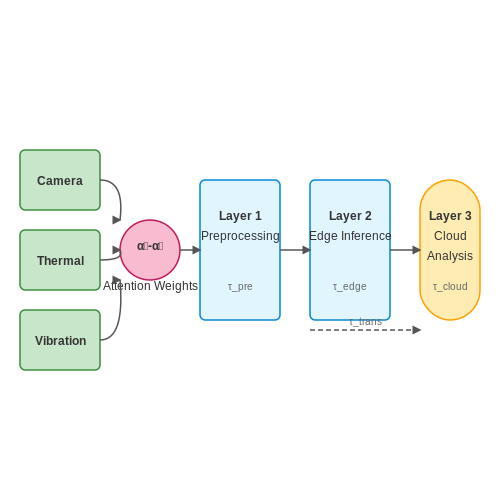
Edge AI systems for defect classification require a distributed architecture that balances computational load between edge devices and cloud servers. The optimal partitioning of inference tasks depends on latency constraints, model complexity, and available hardware. A typical edge-cloud hierarchy consists of:
- Layer 1: On-device preprocessing (noise filtering, normalization)
- Layer 2: Lightweight model inference (binary defect detection)
- Layer 3: Cloud-based detailed classification (multi-class analysis)
Where \(\tau_{pre}\) is preprocessing time, \(\tau_{edge}\) is edge inference latency, \(\tau_{trans}\) is data transmission delay, and \(\tau_{cloud}\) is cloud processing time. For real-time applications (\(\tau_{total} < 100ms\)), the edge component must handle at least 80% of inference tasks.
Model Optimization Techniques
Quantization-aware training and pruning are essential for deploying CNNs on edge devices. Post-training quantization reduces model size by converting 32-bit floats to 8-bit integers:
Where \(n\) is the target bit-width (typically 8). This reduces memory requirements by 4× with minimal accuracy loss (\(\leq 2\%\)) when combined with calibration datasets. Channel pruning removes redundant filters by evaluating their \(L_1\)-norm contribution:
IoT Sensor Fusion for Defect Detection
Multi-modal sensor arrays improve detection robustness by combining:
- High-resolution cameras (200-1000 fps) for surface defects
- Thermal imaging (\(\pm0.1°C\) resolution) for material inconsistencies
- Vibration sensors (10-20 kHz) for structural flaws
The sensor fusion pipeline employs attention mechanisms to weight modalities dynamically:
Where \(h_i\) are hidden states and \(s_i\) are sensor reliability scores.
Hardware Accelerators for Edge Deployment
FPGA-based implementations achieve 5-10× better energy efficiency than GPUs for CNNs. A typical Vision Transformer (ViT) deployment on Xilinx Zynq UltraScale+ MPSoC achieves:
- 4.3 TOPS/W power efficiency
- 23 ms latency for 512×512 images
- 8-bit integer precision with hybrid quantization
The computational throughput \(C\) scales with parallel processing elements (PEs):
Where \(N_{PE}\) is the number of PEs (typically 64-256), \(f_{clk}\) is clock frequency (200-500 MHz), and OPS/cycle depends on data reuse patterns.
Case Study: Automotive Paint Defect Detection
A production line implementation using NVIDIA Jetson AGX Orin (32 TOPS) and FLIR Boson thermal cameras achieved:
- 99.2% recall for scratches >50μm
- 97.8% precision across 12 defect classes
- 83 ms end-to-end latency per vehicle panel
The system processes 24 MPixel/s using a pruned MobileNetV3 backbone with depthwise separable convolutions:
Where \(K\) is kernel size, \(C\) are channels, and \(H,W\) are spatial dimensions. This reduces computations by 18× compared to standard convolutions.
7. Key Research Papers and Articles
7.1 Key Research Papers and Articles
- An Industrial Case Study of Implementing and Validating Defect ... — Classifying the origin of a defect is one example of defect classification in gen-eral. A defect classification scheme contains one or more defect classification attributes that capture various aspects of a defect. For example, [18] proposes a framework of eight high-level key attributes that capture different defect as-pects. Each of these ...
- PDF Using Deep Learning to Detect Defects in Manufacturing: A Comprehensive ... — Abstract: The detection of product defects is essential in quality control in manufacturing. This study surveys stateoftheart deep-learning methods in defect detection. First, we classify the defects of products, such as electronic components, pipes, welded parts, and textile materials, into categories.
- Using Deep Learning to Detect Defects in Manufacturing: A Comprehensive ... — Industrial product quality is an important part of product production, and the research on defect-detection technology has great practical significance to ensure product quality. This article provides a comprehensive overview of the research status of product defect-detection technology in complex industrial processes.
- Intelligent Machine Vision Model for Defective Product ... - MDPI — Quality control is one of the industrial tasks most susceptible to be improved by implementing technological innovations. As an innovative technology, machine vision enables reliable and fast 24/7 inspections and helps producers to improve the efficiency of manufacturing operations. The accessible data by vision equipment will be used to identify and report defective products, understand the ...
- Zero Defect Manufacturing: A complete guide for advanced and ... — Fig. 5 illustrates the five areas related to quality in a manufacturing system, the root of traditional QM methods' classification of quality across product, service, manufacturing process, management, and personnel (Fig. 3). Here, product quality has two further sub-categories: product design and product manufacturing.
- PDF Standard Operating Procedure - GMP SOP — - Identification of defects and their respective AQLs (Acceptable Quality Limits) - Actions that must be taken when critical, major or minor defects are encountered during the Production/ Packaging Process. Note: SOP . QMS-150 . covers the . Classification of Defects for Incoming Packaging Components. 4.0 . RESPONSIBILITY \ BUSINESS RULES . 4.1
- Toward surface defect detection in electronics manufacturing by an ... — In electronics manufacturing, surface defect detection is very important for product quality control, and defective products can cause severe customer complaints. At the same time, in the ...
- Computer vision defect detection on unseen backgrounds for ... — Research on defect-detection technology can reduce the production cost, ... The key difference here is that the defects appeared in a diverse set of parts, forcing the model to focus on learning a set of features that was invariant to the background - i.e. the defect itself. ... A CNN-based transfer learning method for defect classification in ...
- Deep Learning for Detecting Manufacturing Defects Using Convolutional ... — In the research paper, a simple Convolutional Neural Network (CNN) model with two convolutional layers is proposed for image classification. The model is based on the LeNet 5 architecture. The proposed simple Convolutional Neural Network (CNN) model, inspired by LeNet 5, employs two convolutional layers for casting piece defect classification.
- Review on system development in eddy current testing and technique for ... — The crack defect classification often used in the design of electromagnetic problems where the goal is to find a topology change rather than to determine the surface shape. For example, in NDT applications, it is more important to know the number and location of all the flaws in the specimen than to find the right form cracked only specimen.
7.2 Industry Case Studies
- Visual analytics and intelligent reasoning for smart manufacturing ... — Visual analytics and intelligent reasoning for smart manufacturing defect detection and judgement: A meta-learning approach with knowledge graph embedding case-based reasoning ... which is commonly seen in electronics products. ... The training results of Xception for binary classification and defect classification are shown in Figs. 11 and 12 ...
- Deep Learning for Detecting Manufacturing Defects Using ... - Springer — Several studies have explored the effectiveness of Convolutional Neural Networks (CNNs) for defect detection and classification in different manufacturing contexts. Berger et al. [ 1 ] apply deep learning for surface inspection in the automotive industry using CNNs, enhancing defect detection precision and demonstrating adaptability in ...
- Using Deep Learning to Detect Defects in Manufacturing: A ... - MDPI — The detection of product defects is essential in quality control in manufacturing. This study surveys stateoftheart deep-learning methods in defect detection. First, we classify the defects of products, such as electronic components, pipes, welded parts, and textile materials, into categories. Second, recent mainstream techniques and deep-learning methods for defects are reviewed with their ...
- Using Deep Learning to Detect Defects in Manufacturing: A Comprehensive ... — The detection of product defects is essential in quality control in manufacturing. This study surveys stateoftheart deep-learning methods in defect detection. First, we classify the defects of products, such as electronic components, pipes, welded parts, and textile materials, into categories.
- An Industrial Case Study of Implementing and Validating Defect ... — Classifying the origin of a defect is one example of defect classification in gen-eral. A defect classification scheme contains one or more defect classification attributes that capture various aspects of a defect. For example, [18] proposes a framework of eight high-level key attributes that capture different defect as-pects. Each of these ...
- Computer vision defect detection on unseen backgrounds for ... — In recent years, deep learning has been applied to industrial defect classification in various fields, including industrial production and electronic components. For supervised steel defect classification, a max-pooling CNN approach was proposed in Masci et al. (2012). The CNN outperformed SVM classifiers and functioned correctly with different ...
- Intelligent Machine Vision Model for Defective Product ... - MDPI — Quality control is one of the industrial tasks most susceptible to be improved by implementing technological innovations. As an innovative technology, machine vision enables reliable and fast 24/7 inspections and helps producers to improve the efficiency of manufacturing operations. The accessible data by vision equipment will be used to identify and report defective products, understand the ...
- PDF Standard Operating Procedure - GMP SOP — - Identification of defects and their respective AQLs (Acceptable Quality Limits) - Actions that must be taken when critical, major or minor defects are encountered during the Production/ Packaging Process. Note: SOP . QMS-150 . covers the . Classification of Defects for Incoming Packaging Components. 4.0 . RESPONSIBILITY \ BUSINESS RULES . 4.1
- PDF Automotive Zero Defects Framework — Automotive Electronics Council ZERO DEFECTS FRAMEWORK 1. SCOPE This document provides a framework to be used in the definition of a strategy towards Zero Defects (ZD) of any semiconductor product in the scope of the AEC-Q100, -Q101, -Q102, -Q103, and -Q104 standards and, where applicable, passive components in AEC-Q200. The list of processes ...
- PDF Defect Detection and Classification in Printed Circuit Boards using ... — Fig. 5. Evaluation Results. f) Spur: The model's first training loss is high at 1.7, suggesting a significant initial variance between its predictions and the actual data. However, the loss ...
7.3 Recommended Books and Online Resources
- Reliability of Electronic Components A Practical Guide To Electronic ... — Reliability of Electronic Components a Practical Guide to Electronic Systems Manufacturing - Free download as PDF File (.pdf), Text File (.txt) or read online for free. ... 7.3.1 Failure mechanisms 224 7.3.1.1 Gate oxide breakdown 225 7.3.1.2 Surface charges 226 7.3.1.3 Hot carrier ... product, etc. The best product may not be taken into ...
- PDF Automotive Zero Defects Framework — This document provides a framework to be used in the definition of a strategy towards Zero Defects (ZD) of any semiconductor product in the scope of the AEC-Q100, -Q101, -Q102, -Q103, and -Q104 ... product design, production, and product/manufacturing Improvement, as depicted in Figure 1. ... 3.7, 3.8 JEP150 Stress Test Drive Qualification of ...
- Reliability and Failure of Electronic Materials and Devices, 2nd ... — Book description Reliability and Failure of Electronic Materials and Devices is a well-established and well-regarded reference work offering unique, single-source coverage of most major topics related to the performance and failure of materials used in electronic devices and electronics packaging. With a focus on statistically predicting failure and product yields, this book can help the ...
- PDF Rework, Modification and Repair of Electronic Assemblies - IPC — and Repair of Electronic Assemblies If a conflict occurs between the English language and translated ... take precedence. Developed by the Repairability Subcommittee (7-34) of the Product Assurance Committee (7-30) of IPC Users of this publication are encouraged to participate in the ... 7711-7 3.1.5 Through-Hole Desoldering — Full Clinch ...
- IPC A 610 Flashcards - Quizlet — Study with Quizlet and memorize flashcards containing terms like Class 1 Product, Class 2 Product, Class 3 Product and more. ... Dedicated Service Electronic Product - Continued performance and extended life required. Uninterrupted service is desired but not required. ... A defect for Class 2 implies a defect for Class 3. Disposition.
- PDF Electrical, Electronic, and Electromechanical (Eee) Parts ... - Nasa — NASA-STD-8739.10—2017-06-13 7 of 39 1.3 Tailoring 1.3.1 Tailoring of the requirements contained in this standard for application to a specific program or project per Center requirements, risk classification or acceptable risk posture shall be
- PDF Standard Operating Procedure - GMP SOP — - Identification of defects and their respective AQLs (Acceptable Quality Limits) - Actions that must be taken when critical, major or minor defects are encountered during the Production/ Packaging Process. Note: SOP . QMS-150 . covers the . Classification of Defects for Incoming Packaging Components. 4.0 . RESPONSIBILITY \ BUSINESS RULES . 4.1
- PDF Booklet No. 14 Failure Mode and Effects Analysis FMEA - Bosch Global — In the application of the FMEA, it is distinguished between the Product FMEA and the Process FMEA. Product and Process FMEA cover all terms appertaining to the FMEA, such as system, interface, design, production, assembly, logistics and machine FMEA, for example. The FMEA may also be universally used for non-technical processes. 2.1. Product FMEA
- Acceptability of Electronic Assemblies (IPC A-610J-2024) — A defect for Class 1 automatically implies a defect for Class 2 and 3. A defect for Class 2 implies a defect for Class 3. Criteria are given for each class in three conditions: Acceptable, Defect, or Process Indicator. IPC A-610J-2024: Acceptability Of Electronic Assemblies is available on the ANSI Webstore. Please note that this standard ...
- PDF IPC-A-610G: Acceptability of Electronic Assemblies table of contents — IPC-A-610G Acceptability of Electronic Assemblies Developed by the IPC-A-610 Task Group (7-31b) of the Acceptability Subcommittee (7-31) of the Product Assurance Committee (7-30) of IPC