
Automatic timer switch with ua741

The circuit described encompasses multiple functionalities, primarily focusing on voltage comparison and timing operations. The UA741 operational amplifier is a versatile component, often used in analog applications for signal amplification and comparison. In this configuration, it is crucial for determining the conditions under which the relay is activated or deactivated based on the voltage levels at its inputs.
The voltage divider formed by R3 and R4 is essential for establishing a stable reference voltage at pin 3 of the UA741. The reference voltage is compared with the voltage at pin 2, which is influenced by the voltage drop across capacitor C2. The delay introduced by the combination of VR1, R1, and C2 ensures that the system can maintain its state for a predetermined period, effectively managing the timing of relay activation.
The use of the 555 timer IC is notable for its reliability and ease of use in timing applications. By adjusting VR1, the timing can be fine-tuned for specific requirements, making this circuit adaptable for various applications. The integration of the 2N4871 transistor serves a critical protective role, mitigating potential damage from voltage spikes during power cycling.
The inclusion of a MOSFET for the OFF After Delay Switch Circuit highlights the versatility of modern electronic components, allowing for efficient control of loads with minimal power loss. This aspect is particularly beneficial in applications where energy efficiency is paramount.
Overall, this circuit design exemplifies a well-thought-out approach to managing timing and voltage comparison tasks, ensuring both functionality and protection for connected devices.When the switch S1 / 2 power input to the circuit C1 No. ua741. To a voltage comparison circuit. The pin 3 is the noninverting pin. for pin 2 to pin inverting. The pin 3 was divided voltage from R3 and R4. Used as a reference voltage for comparing the voltage at Pin 2 And the voltage drop across C2. The VR1, R1 and C2 is set to delay. To set up a lon g time. I add the R1 and C2. The switch S1 / 1 to determine the C2 discharge through R10 out. To start new work while off. The switch S1 / 1 and S1 / 2 are in the same But working conditions are opposite. 555 IC Timer control relay SwitchThis is easy Timer circuit projects. Control by relay. It use IC 555. This the circuit sets the time to are simple one that interesting, because use IC LM555 Timer be 8 pin integrated circuits. But can set the time accurate can use by fine while VR1 [. ] Switch off delay circuit by 2N4871 This circuit prevents surges. From the opening is switched off or power failure. The damage to electrical appliances. The circuit will switch to use a short period before Power raising circuit to go. [. ] OFF After Delay Switch by MosfetThis is OFF After Delay Switch Circuit. It is use Mosfet control the work of LOAD get. By have the work is simple be press Switch (Close) and liberate (Open) S1 an electric bell will loud.
[. ] We aim to transmit more information by carrying articles. Please send us an E-mail to wanghuali@hqew. net within 15 days if we are involved in the problems of article content, copyright or other problems. We will delete it soon. 🔗 External reference
Related Circuits
The installation of security cameras in offices, homes, or shops has become economically viable due to the decreasing prices of security cameras. However, it is not efficient if we... The integration of security cameras into various environments such as offices,...
In certain locations near the reservoir or well, when the water level is constrained by the water towers, there is a need for simultaneous monitoring of the water towers and reservoirs as part of an automatic water control system....

By utilizing a high-gain, high-impedance operational amplifier, it is possible to construct a long time delay circuit using a resistor-capacitor (RC) configuration, as it allows for high... An operational amplifier (op-amp) is a versatile component widely used in electronic circuits,...

A 5V Switch Mode Power Supply utilizing the LM2674 power supply. Refer to the corresponding page for an explanation of the related circuit diagram. The 5V Switch Mode Power Supply (SMPS) designed with the LM2674 integrates a step-down (buck) converter...

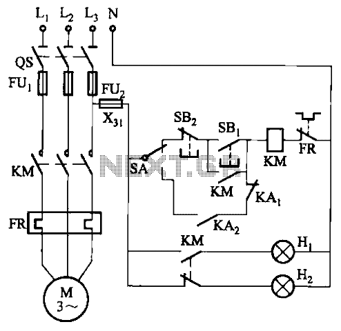
The circuit illustrated in Figure 3-64 operates with switch SA1 in the work position and switch SA2 in the standby position, allowing motor Mi to run while motor Mz remains on standby. In the event of downtime for motor...

This sensitive sound-operated switch can be used with a dynamic microphone insert or with an electret (ECM) microphone. If an ECM is used, then R1 (shown dotted) will need to be included, with a suitable value between 2.2k and...