


Bistable Multivibrators
#CMOS
#flip flop
#CD4013
#relay
#push button
#bistable
#multivibrator
#toggle switch
#momentary switch
#logic circuit

Description: The circuit utilizes a CMOS dual D flip-flop (CD4013) to toggle a relay or other load using a momentary push button. Multiple push buttons can be connected in parallel to control the relay from different locations. A high signal from the push button is coupled to the set line through a small capacitor (0.1 µF). The high level from the Q output is inverted by the upper transistor, providing a low reset signal to the reset line for approximately 400 ms, after which the reset line returns to a high state, resetting the flip-flop.
The circuit employs a CMOS dual D flip-flop (CD4013) to toggle a relay or similar load via a momentary push button. This configuration allows for multiple push buttons to be connected in parallel, enabling control of the relay from various locations. When the push button is activated, a high signal is transmitted to the set line through a coupling capacitor of 0.1 µF. The output from the Q terminal is then inverted by an upper transistor, generating a low reset signal that is applied to the reset line for a duration of approximately 400 milliseconds. After this interval, the reset line reverts to a high state, thereby resetting the flip-flop.
In this circuit, the CD4013 flip-flop acts as a bistable element, maintaining its state until triggered by the push button. The momentary high signal initiates a state change, allowing for the toggling of the relay. The use of a capacitor in conjunction with the push button ensures that the signal is appropriately managed, preventing noise and ensuring reliable operation.
The reset mechanism provided by the upper transistor ensures that the flip-flop returns to its original state after a specified time, which can be useful in applications where a temporary activation of the relay is required. The design can be adapted for various applications, including remote control systems, alarm systems, and other scenarios where momentary actuation is beneficial.
The flexibility of wiring multiple push buttons in parallel enhances the usability of this circuit, allowing for control from different locations without the need for complex wiring or additional components. Overall, this circuit exemplifies a straightforward yet effective implementation of a toggle mechanism using a dual D flip-flop and demonstrates the versatility of CMOS technology in digital circuit design.The circuit below uses a CMOS dual D flip flop (CD4013) to toggle a relay or other load with a momentary push button. Several push buttons can be wired in parallel to control the relay from multiple locations. A high level from the push button is coupled to the set line through a small (0. 1uF) capacitor. The high level from the Q output is inverted by the upper transistor and supplies a low reset level to the reset line for about 400 mS, after which time the reset line returns to a high state and resets the flip flop. CMOS Toggle Flip Flop Using Push Button - The circuit below uses a CMOS dual D flip flop (CD4013) to toggle a relay or other load with a momentary push button.
Several push buttons can be wired in parallel to control the relay from multiple. DAC & flip flops form constant current source - 04/23/09 EDN- Design Ideas, Using two flip flops, you can program a serial-input DAC to produce a constant 4 mA. Descrete Set/Reset Flip Flop - Here are two examples of bistable flip flops which can be toggled between states with a single push button.
When the button is pressed, the capacitor connected to the base of the conducting transistor will charge to a slightly higher voltage. When the button is released, the same capacitor will discharge back to the previous voltage causing the transistor to turn off.
The rising voltage at the collector of the transistor that is turning off causes the opposite transistor to turn on and the circuit remains in a stable state until. D-Flip/Flop One Shot Circuit - Yes you can use cheap D flip/flop logic circuits as nice one-shot pulse generators.
This schematic shows how the popular CD4013 and the CD74HC74 can be used to generate pulses ranging from nanoseconds to seconds. Discrete Set/Reset Flip Flop - This is an example of a set/reset flip flop using discrete components.
When power is applied, only one of the transistors will conduct causing the other to remain off. The conducting transistor can be turned off by grounding it`s base through the push button which causes the collector voltage to rise and turn on the opposite transistor. Flashing LED Advertising Badge #1 - I have seen numerous flashing light badges at trade shows and conventions.
They are often handed out as gifts to promote some business. The devices often use inefficient circuits, which cause the battery power source to be quickly depleted. My circuit is simple but efficient enough to provide months of continuous LED flashing. It also has a tiny push-button switch to turn on and off the light flashing, extending battery power.
Flashing LED Advertising Badge #2 - This circuit is similar to flashing LED advertising badge #1. . It uses a CD4013 dual D Flip/Flop IC. The 74HCT74 IC in #81 does not always work. As in #81, a single lithium battery will provide months of continuous LED flashing. It also has a tiny push-button switch to turn on and off the light flashing. Flip Flop Circuit - In this project we examine one of the most valuable circuits to be invented, the flip flop. Originally it was designed with VALVES, along with its simpler version (without the two capacitors, called a bi-stable Multivibrator), it was realised it.
Flip Flop Flashers Buzzers Etc - Several circuits here. The familiar astable flip-flop circuit is a handy configuration for making flashers or generating squarewaves. Here is a typical alternating LED flasher with the LEDs in the emitters instead of collectors as is normally done.
The bias resistors are directly connected. FPGA implements X. 50 Division 3 recommendation - EDN-Design Ideas: The scheme in Figure 1a uses five delay cells and an XOR gate to configure the data stream for the X. 50 Division 3 recommendation of ITU-T. The X. 50 recommendation defines the fundamental parameters of a multiplexing scheme for inter working data High Current MOSFET Flip Flop with Debounced Pushbutton - This
The circuit employs a CMOS dual D flip-flop (CD4013) to toggle a relay or similar load via a momentary push button. This configuration allows for multiple push buttons to be connected in parallel, enabling control of the relay from various locations. When the push button is activated, a high signal is transmitted to the set line through a coupling capacitor of 0.1 µF. The output from the Q terminal is then inverted by an upper transistor, generating a low reset signal that is applied to the reset line for a duration of approximately 400 milliseconds. After this interval, the reset line reverts to a high state, thereby resetting the flip-flop.
In this circuit, the CD4013 flip-flop acts as a bistable element, maintaining its state until triggered by the push button. The momentary high signal initiates a state change, allowing for the toggling of the relay. The use of a capacitor in conjunction with the push button ensures that the signal is appropriately managed, preventing noise and ensuring reliable operation.
The reset mechanism provided by the upper transistor ensures that the flip-flop returns to its original state after a specified time, which can be useful in applications where a temporary activation of the relay is required. The design can be adapted for various applications, including remote control systems, alarm systems, and other scenarios where momentary actuation is beneficial.
The flexibility of wiring multiple push buttons in parallel enhances the usability of this circuit, allowing for control from different locations without the need for complex wiring or additional components. Overall, this circuit exemplifies a straightforward yet effective implementation of a toggle mechanism using a dual D flip-flop and demonstrates the versatility of CMOS technology in digital circuit design.The circuit below uses a CMOS dual D flip flop (CD4013) to toggle a relay or other load with a momentary push button. Several push buttons can be wired in parallel to control the relay from multiple locations. A high level from the push button is coupled to the set line through a small (0. 1uF) capacitor. The high level from the Q output is inverted by the upper transistor and supplies a low reset level to the reset line for about 400 mS, after which time the reset line returns to a high state and resets the flip flop. CMOS Toggle Flip Flop Using Push Button - The circuit below uses a CMOS dual D flip flop (CD4013) to toggle a relay or other load with a momentary push button.
Several push buttons can be wired in parallel to control the relay from multiple. DAC & flip flops form constant current source - 04/23/09 EDN- Design Ideas, Using two flip flops, you can program a serial-input DAC to produce a constant 4 mA. Descrete Set/Reset Flip Flop - Here are two examples of bistable flip flops which can be toggled between states with a single push button.
When the button is pressed, the capacitor connected to the base of the conducting transistor will charge to a slightly higher voltage. When the button is released, the same capacitor will discharge back to the previous voltage causing the transistor to turn off.
The rising voltage at the collector of the transistor that is turning off causes the opposite transistor to turn on and the circuit remains in a stable state until. D-Flip/Flop One Shot Circuit - Yes you can use cheap D flip/flop logic circuits as nice one-shot pulse generators.
This schematic shows how the popular CD4013 and the CD74HC74 can be used to generate pulses ranging from nanoseconds to seconds. Discrete Set/Reset Flip Flop - This is an example of a set/reset flip flop using discrete components.
When power is applied, only one of the transistors will conduct causing the other to remain off. The conducting transistor can be turned off by grounding it`s base through the push button which causes the collector voltage to rise and turn on the opposite transistor. Flashing LED Advertising Badge #1 - I have seen numerous flashing light badges at trade shows and conventions.
They are often handed out as gifts to promote some business. The devices often use inefficient circuits, which cause the battery power source to be quickly depleted. My circuit is simple but efficient enough to provide months of continuous LED flashing. It also has a tiny push-button switch to turn on and off the light flashing, extending battery power.
Flashing LED Advertising Badge #2 - This circuit is similar to flashing LED advertising badge #1. . It uses a CD4013 dual D Flip/Flop IC. The 74HCT74 IC in #81 does not always work. As in #81, a single lithium battery will provide months of continuous LED flashing. It also has a tiny push-button switch to turn on and off the light flashing. Flip Flop Circuit - In this project we examine one of the most valuable circuits to be invented, the flip flop. Originally it was designed with VALVES, along with its simpler version (without the two capacitors, called a bi-stable Multivibrator), it was realised it.
Flip Flop Flashers Buzzers Etc - Several circuits here. The familiar astable flip-flop circuit is a handy configuration for making flashers or generating squarewaves. Here is a typical alternating LED flasher with the LEDs in the emitters instead of collectors as is normally done.
The bias resistors are directly connected. FPGA implements X. 50 Division 3 recommendation - EDN-Design Ideas: The scheme in Figure 1a uses five delay cells and an XOR gate to configure the data stream for the X. 50 Division 3 recommendation of ITU-T. The X. 50 recommendation defines the fundamental parameters of a multiplexing scheme for inter working data High Current MOSFET Flip Flop with Debounced Pushbutton - This

R/C On/Off Motor Controller with Brake
A relay-based on/off controller on the other hand can be very efficient. A typical relay has a contact resistance of 3 milliOhm. At 20A, this translates to a voltage drop of 0.06 volts, with a power loss of 1.2W. The...

Trigger multivibrator circuit diagram
Each trigger input can produce a fixed number of pulses, with the range being from 2 to 30. The specific number is determined by the frequency-controlled settings of 1 megohm. A monostable gated unsteady power supply circuit can be achieved...

Multi Switch Controlled Relay
A Multi Switch Controlled Relay circuit is utilized to manage home appliances, featuring a circuit diagram that outlines the application of a multi switch-controlled relay using a single integrated circuit (IC) for various control functions.
The Multi Switch Controlled Relay circuit...

Quiz Circuit
This design utilizes four integrated circuits (ICs) and features four input circuits with four independent outputs, along with a single master reset switch. The outputs are configured with light-emitting diodes (LEDs), which can be modified to control lamps or buzzers....
relay In a circuit being switched by an NPN transistor do power supply and input need the same ground
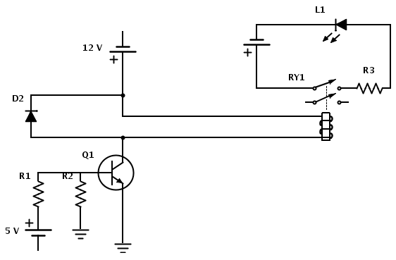
Create a circuit that enables the activation of a relay to control an LED. The relay operates at 12 V, while the available input voltage is 5 V. An NPN transistor will be utilized to switch the power to the...

Power Control Unit
This shows the overall circuit diagram of the power control unit. On the left, there is a main relay controlled by the key switch.
The power control unit circuit diagram illustrates the primary components and their interconnections for managing electrical power...

Cmos programmable divide-by-n counter
A single connection change allows division by any integer between 2 and 10. The RCA CD4017A Johnson decade counter is configured as a divide-by-7 counter. A resistor is utilized to maintain the reset line in a low state. When the...

Power-Off Time Delay Relay circuit
The two circuits demonstrate the process of opening a relay contact shortly after the ignition or light switch is turned off. The capacitor is charged, and the relay remains closed until the voltage at the diode anode reaches +12 volts.
The...

Night security light
This simple circuit is built around a CMOS IC 4060 to obtain the required timing. During daytime, the LDR has low resistance and keeps pin 12 of IC1 high, preventing IC1 from oscillating. When it is dark, the LDR resistance...