


555 automatic power-protection circuit diagram
#555 timer
#overvoltage protection
#undervoltage protection
#power protection
#delay switch
#rectifier
#voltage detection
#automatic control
#circuit protection

Description: An automatic power protection circuit is presented. This protection includes a step-down rectifier circuit, an overvoltage and undervoltage detection circuit, and a delay switch control circuit. The step-down circuit is responsible for the entire rectifier circuit's DC voltage.
The automatic power protection circuit is designed to safeguard electronic devices from voltage fluctuations that could potentially cause damage. The step-down rectifier circuit serves as the initial stage, converting the input AC voltage to a lower DC voltage suitable for the subsequent components. This step-down operation is crucial in ensuring that the voltage levels remain within safe operating limits.
The overvoltage and undervoltage detection circuits are integrated to monitor the output voltage continuously. They employ voltage sensing mechanisms to detect any deviations from the predefined voltage thresholds. When an overvoltage condition is detected, the circuit activates protective measures, such as disconnecting the load or triggering an alarm, to prevent damage to the connected devices. Conversely, in the event of undervoltage, the circuit can initiate a shutdown procedure to safeguard the equipment from insufficient voltage levels that could lead to malfunction or damage.
The delay switch control circuit plays a vital role in managing the timing of the power restoration after a fault condition has been detected. This delay is essential to allow transient conditions to stabilize before reapplying power to the load. It prevents unnecessary cycling of the power, which could lead to further issues.
Overall, this automatic power protection circuit is an essential component in modern electronic systems, providing robust protection against voltage anomalies and ensuring the reliability and longevity of sensitive electronic devices.Shown automatic power-protection circuit. This protection consists of step-down rectifier circuit, overvoltage and undervoltage detection circuit, delay switch control circuit. Wherein the step-down circuit for the entire rectifier circuit DC voltage.
The automatic power protection circuit is designed to safeguard electronic devices from voltage fluctuations that could potentially cause damage. The step-down rectifier circuit serves as the initial stage, converting the input AC voltage to a lower DC voltage suitable for the subsequent components. This step-down operation is crucial in ensuring that the voltage levels remain within safe operating limits.
The overvoltage and undervoltage detection circuits are integrated to monitor the output voltage continuously. They employ voltage sensing mechanisms to detect any deviations from the predefined voltage thresholds. When an overvoltage condition is detected, the circuit activates protective measures, such as disconnecting the load or triggering an alarm, to prevent damage to the connected devices. Conversely, in the event of undervoltage, the circuit can initiate a shutdown procedure to safeguard the equipment from insufficient voltage levels that could lead to malfunction or damage.
The delay switch control circuit plays a vital role in managing the timing of the power restoration after a fault condition has been detected. This delay is essential to allow transient conditions to stabilize before reapplying power to the load. It prevents unnecessary cycling of the power, which could lead to further issues.
Overall, this automatic power protection circuit is an essential component in modern electronic systems, providing robust protection against voltage anomalies and ensuring the reliability and longevity of sensitive electronic devices.Shown automatic power-protection circuit. This protection consists of step-down rectifier circuit, overvoltage and undervoltage detection circuit, delay switch control circuit. Wherein the step-down circuit for the entire rectifier circuit DC voltage.

TRAFFIC LIGHT SEQUENCER CIRCUIT
This circuit utilizes a 555 timer to control a 4017 decade counter. The outputs from the counter are used to drive transistor relay drivers. The duration for which the lights remain "on" can be adjusted by modifying the connections of...
circuit alarm
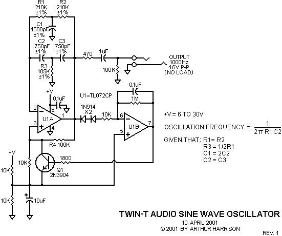
The circuit can be constructed using a pair of twin-T oscillators, with the Q factor adjusted to the threshold of oscillation, allowing them to resonate like a bell when activated by a voltage pulse. Each twin-T oscillator is designated for...

HV Ignition Coil Driver using 555
A simple design based on a 555 to drive a car ignition coil. This was designed for a small electric fence to protect a vegetable garden from small animals called marmots. Last year, they ate one of the crops entirely...

theft preventer alarm circuit
This circuit utilizes a 555 timer integrated circuit (IC) to function as an alarm system designed to deter theft of personal belongings, such as luggage, or to prevent unauthorized entry into a residence. The alarm is activated when a thin...

Three-phase controlled rectifier circuit
Trigger circuit routing forms include various types such as simple trigger circuits, single-junction transistor trigger circuits, synchronous sine wave trigger circuits, sawtooth transition phase shift (synchronous) trigger circuits, and integrated trigger circuits. This section presents individual cases for introduction due...

Non-standard 555 Astable Multivibrator
A square wave generator with a variable frequency and a 50% duty cycle is required. While the 555 timer is a common choice, the standard astable multivibrator configuration alters the duty cycle when the frequency is adjusted. A circuit found...
Inductorless Power Supply Converter Circuit
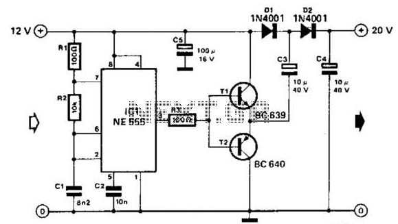
Using a 555 timer and voltage doubler, this circuit will supply over 50 mA at 20 V DC. Transistors T1 and T2 act as power amplifiers to drive the voltage doubler. The frequency of operation is approximately 8.5 kHz.
The circuit...

LED Flasher Circuit
The 555 timer chip is a versatile integrated circuit (IC) that, when connected correctly, can generate pulses of current at specific intervals determined by a resistor-capacitor (RC) network. In this mode, the LED does not remain constantly lit; it turns...

555 ASTABLE_FREQUENCY METER
The circuit illustrated is a straightforward digital frequency meter that displays the frequency in hertz of an astable 555 timer. It may potentially be modified for alternative applications. An NPN transistor, TR2, is linked to the 555 astable timer being...