


555 timer Door minder electronic project circuit diagram
#555 timer
#IR beam
#relay
#door sensor
#alarm
#security
#motion detection
#electronic project
#circuit diagram

Description: This door minder electronic project is based on a 555 timer circuit and utilizes an infrared (IR) beam to monitor doorways, passageways, or any other designated area. When the IR beam is interrupted, a relay is activated, which can be employed to trigger a bell or alarm. This project is particularly suitable for detecting customers entering a shop or cars approaching a driveway. The IR beam is capable of monitoring distances exceeding 25 yards. The receiver module comprises an IR receiver that detects the incoming beam from the transmitter. The IR signal is utilized to maintain a capacitor in a charged state, which in turn keeps the relay activated. When the beam is broken, the capacitor discharges, resulting in the relay deactivating. This circuit requires a 12-volt DC power supply.
The door minder project employs a 555 timer IC configured in a monostable mode, ensuring that the relay remains energized while the IR beam is intact. The IR transmitter typically consists of an IR LED that emits a continuous beam, while the IR receiver includes a photodiode or phototransistor that detects the presence of the beam. The design allows for a robust detection range, making it suitable for various applications, including security systems and automated entry alerts.
The circuit requires a stable 12V DC power supply to function correctly. Upon powering the circuit, the 555 timer's output pin is connected to the relay's coil, allowing the relay to close its contacts and activate the connected bell or alarm when the IR beam is uninterrupted. The capacitor in the circuit serves as a timing element, ensuring that the relay remains activated for a predetermined duration even after the beam is momentarily interrupted.
To enhance the reliability of the system, it is advisable to incorporate a resistor-capacitor (RC) filter at the output of the IR receiver to eliminate noise and false triggering. Additionally, the circuit can be fine-tuned by adjusting the values of the resistor and capacitor associated with the 555 timer to modify the response time and sensitivity of the system.
In conclusion, this door minder electronic project effectively utilizes a 555 timer circuit and an IR beam for monitoring entry points, providing a practical solution for detecting movement in a specified area while ensuring ease of installation and operation.This door minder electronic project is based on a 555 timer circuit and uses an IR beam to monitor door and passage-ways or any other area. When the IR beam is broken a relay is tripped which can be used to sound a bell or alarm. This door minder electronic project is suitable for detecting customers entering a shop, cars coming up a driveway, etc
. Because the IR beam is very strong distances over 25 yards can be monitored with electronic circuit. The receiver module consists of an IR receiver module that detects the incoming beam from the transmitter. The IR signal is used to keep a capacitor charged which in turn holds a relay operated. When the beam is broken the capacitor discharges and the relay releases. This circuit must be powered from a 12volt DC supply.
The door minder project employs a 555 timer IC configured in a monostable mode, ensuring that the relay remains energized while the IR beam is intact. The IR transmitter typically consists of an IR LED that emits a continuous beam, while the IR receiver includes a photodiode or phototransistor that detects the presence of the beam. The design allows for a robust detection range, making it suitable for various applications, including security systems and automated entry alerts.
The circuit requires a stable 12V DC power supply to function correctly. Upon powering the circuit, the 555 timer's output pin is connected to the relay's coil, allowing the relay to close its contacts and activate the connected bell or alarm when the IR beam is uninterrupted. The capacitor in the circuit serves as a timing element, ensuring that the relay remains activated for a predetermined duration even after the beam is momentarily interrupted.
To enhance the reliability of the system, it is advisable to incorporate a resistor-capacitor (RC) filter at the output of the IR receiver to eliminate noise and false triggering. Additionally, the circuit can be fine-tuned by adjusting the values of the resistor and capacitor associated with the 555 timer to modify the response time and sensitivity of the system.
In conclusion, this door minder electronic project effectively utilizes a 555 timer circuit and an IR beam for monitoring entry points, providing a practical solution for detecting movement in a specified area while ensuring ease of installation and operation.This door minder electronic project is based on a 555 timer circuit and uses an IR beam to monitor door and passage-ways or any other area. When the IR beam is broken a relay is tripped which can be used to sound a bell or alarm. This door minder electronic project is suitable for detecting customers entering a shop, cars coming up a driveway, etc
. Because the IR beam is very strong distances over 25 yards can be monitored with electronic circuit. The receiver module consists of an IR receiver module that detects the incoming beam from the transmitter. The IR signal is used to keep a capacitor charged which in turn holds a relay operated. When the beam is broken the capacitor discharges and the relay releases. This circuit must be powered from a 12volt DC supply.

Alarm
This is a simple and easy-to-build multi-tone alarm circuit that can be utilized in burglar alarms or sirens. The circuit is based on the dual op-amp MC1458 and LM380. The two op-amps within the MC1458 are configured to generate square...

Water Activated Sensor Alarm Using 555 PCB
The circuit utilizes a 555 integrated circuit (IC) functioning as an astable multivibrator. When a positive 9 volts is applied to pin 8, the circuit generates sound through a speaker. The connection to pin 8 is routed through a transistor,...

Wide Frequency Range 555 VCO
The frequency of the 555 timer can be adjusted by varying the voltage applied to pin 5. However, the range and linearity of this frequency adjustment are quite limited.
The 555 timer IC is widely used in various applications, including timers,...

Level 555 a control circuit diagram
The level control circuit comprises a step-down rectifier circuit, a trigger circuit utilizing two 555 timer ICs (IC1 and IC2), and a relay control circuit. The rectifier circuit is responsible for providing the necessary DC voltage for the flip-flop IC1,...

Logic level relay controller
The schematic below illustrates 4 methods of controlling a relay with a digital logic signal. Figure (A) can probably be used in most cases where the relay coil requires 100 mA or less and the input current is 2 milliamps...

Cheap fluorescent display circuit 555
The economic fluorescent display circuit is illustrated in the figure. The primary component of this circuit is the 555 timer configured as a multivibrator. The oscillation frequency is determined by the components R1, R2, and C1, with a frequency calculated...

555 Low Voltage Operation
There have been stories regarding the suboptimal performance of the 555 timer IC when operated below a supply voltage (Vcc) of 5V, prompting an investigation into potential improvements for its operation.
The 555 timer IC is a versatile device commonly used...

555 Timer IC for Square Wave Generator Application
The setup for the Square Wave Generator can be initiated using a 555 timer IC as illustrated in the accompanying circuit diagram. It is essential to reference the pinout configuration of the 555 timer IC. An oscilloscope should be connected...
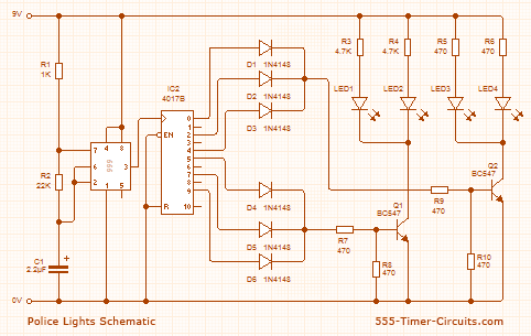
Police Lights associate crystal rectifier Project
This circuit utilizes a 555 timer configured to operate in astable mode. This setup generates a continuous output through Pin 3 in the form of a square wave. When the timer's output transitions to a high state, it triggers the...