


Alternate Tone Alarm Circuit

Description: A two-tone generator that is alternately switched ON provides a high/low output similar to that of a traffic vehicle, such as a police car or ambulance. The CD4011 integrated circuit (IC1), which is a quad 2-input NAND gate, functions as a two-tone oscillator. Each side of the IC, specifically pins 1 through 7 and 8 through 13, sets the tone frequencies. The values of capacitors C9 and C] determine the high and low tones. The output frequencies are coupled to another CD4011 (IC2), where one side (pins 1 through 6) acts as a buffer. This buffer is essential to prevent loading on the outputs that would occur if the signal were sent directly to the LM386 amplifier. The other side of IC2, pins 8 through 13, serves as a slow pulse oscillator generating approximately 8 Hz.
The output at pin 10 of IC2 is connected to IC4, the CD4027, which is a dual J-K master-slave flip-flop configured to function as a toggle switch. The outputs at pins 15 and 14 alternate between high and low states with each positive pulse transition received at pin 13 from IC2. The CD4027 operates in toggle mode when the set and reset inputs (pins 9 and 12) are held low, while the J-K inputs (pins 10 and 11) must be held high. The outputs Q1 and Q1 (NOT) at pins 15 and 14 are connected to pins 13 and 1 of IC1, enabling or disabling the tone oscillators alternately. The final component, IC5, is a simple low-voltage audio amplifier.
The two-tone generator circuit is designed to produce alternating sound signals, mimicking the auditory characteristics of emergency vehicles. The core of the circuit relies on the CD4011 NAND gates, which generate the distinct tone frequencies based on the capacitor values. The choice of capacitors C9 and C] directly influences the audio output, allowing for customization of the high and low tones.
The buffer stage implemented with IC2 ensures that the output from the oscillators does not load down the circuit, which would degrade the sound quality. Instead, it allows for a clean signal to be passed to the LM386 amplifier, which is responsible for amplifying the audio signal to a level suitable for driving a speaker.
The toggle function provided by IC4 enables the user to alternate between the two tones effectively, controlled by the clock signal from IC2. This arrangement allows for a dynamic sound output that can be varied in frequency and amplitude. The overall design of the circuit is straightforward, making it accessible for hobbyists and engineers looking to create auditory signals for alarms or other applications. A two-tone generator that is alternately switched ON provides a high/low output as might be heard from a traffic vehicle like a police car or ambulance. IC1, CD4011, quad 2-input NAND gate is a two-tone oscillator in which each side, pins 1 through 7 and 8 through 13 set the tone frequencies.
Changing the values of C9 and C] determines the high/low tones. The outout frequencies are coupled to IC2, CD4011, of which one side (pins 1 through 6) acts as a buffer. The buffer is necessary to prevent loading on the outputs that would occur if one tried to go directly to the LM386 amplifier.
The other side of IC2, pins 8 through 13, is a slow pulse oscillator of approximately 8 Hz per second. The output at pin 10 is connected to IC4 as a clock. IC4, CD4027, is a dual J-K master-slave flip-flop that is wired to perform as a toggle switch in which Ql and 15, and Ql (NOT) pin 14, go high and low alternately (flip-flop). The clock input from IC2 pin 10 is connected to pin 13 of IC4, and the outputs at pins 15 and 14 changes the flip/flop state with each positive pulse transition.
The CD4027 functions in toggle mode when the set and reset inputs, pins 9 and 12, are held low or grounded. Also, J-K inputs, pins 10 and 11, must be held high or to the positive. The outputs Ql and Ql (NOT), pins 15 and 14 are connected to pins 13 and 1 respectively of IC1 that enables or disables.
Thus, each tone oscillator is turned on and off alternately. ICS is a straightforward low-voltage audio amplifier.
The output at pin 10 of IC2 is connected to IC4, the CD4027, which is a dual J-K master-slave flip-flop configured to function as a toggle switch. The outputs at pins 15 and 14 alternate between high and low states with each positive pulse transition received at pin 13 from IC2. The CD4027 operates in toggle mode when the set and reset inputs (pins 9 and 12) are held low, while the J-K inputs (pins 10 and 11) must be held high. The outputs Q1 and Q1 (NOT) at pins 15 and 14 are connected to pins 13 and 1 of IC1, enabling or disabling the tone oscillators alternately. The final component, IC5, is a simple low-voltage audio amplifier.
The two-tone generator circuit is designed to produce alternating sound signals, mimicking the auditory characteristics of emergency vehicles. The core of the circuit relies on the CD4011 NAND gates, which generate the distinct tone frequencies based on the capacitor values. The choice of capacitors C9 and C] directly influences the audio output, allowing for customization of the high and low tones.
The buffer stage implemented with IC2 ensures that the output from the oscillators does not load down the circuit, which would degrade the sound quality. Instead, it allows for a clean signal to be passed to the LM386 amplifier, which is responsible for amplifying the audio signal to a level suitable for driving a speaker.
The toggle function provided by IC4 enables the user to alternate between the two tones effectively, controlled by the clock signal from IC2. This arrangement allows for a dynamic sound output that can be varied in frequency and amplitude. The overall design of the circuit is straightforward, making it accessible for hobbyists and engineers looking to create auditory signals for alarms or other applications. A two-tone generator that is alternately switched ON provides a high/low output as might be heard from a traffic vehicle like a police car or ambulance. IC1, CD4011, quad 2-input NAND gate is a two-tone oscillator in which each side, pins 1 through 7 and 8 through 13 set the tone frequencies.
Changing the values of C9 and C] determines the high/low tones. The outout frequencies are coupled to IC2, CD4011, of which one side (pins 1 through 6) acts as a buffer. The buffer is necessary to prevent loading on the outputs that would occur if one tried to go directly to the LM386 amplifier.
The other side of IC2, pins 8 through 13, is a slow pulse oscillator of approximately 8 Hz per second. The output at pin 10 is connected to IC4 as a clock. IC4, CD4027, is a dual J-K master-slave flip-flop that is wired to perform as a toggle switch in which Ql and 15, and Ql (NOT) pin 14, go high and low alternately (flip-flop). The clock input from IC2 pin 10 is connected to pin 13 of IC4, and the outputs at pins 15 and 14 changes the flip/flop state with each positive pulse transition.
The CD4027 functions in toggle mode when the set and reset inputs, pins 9 and 12, are held low or grounded. Also, J-K inputs, pins 10 and 11, must be held high or to the positive. The outputs Ql and Ql (NOT), pins 15 and 14 are connected to pins 13 and 1 respectively of IC1 that enables or disables.
Thus, each tone oscillator is turned on and off alternately. ICS is a straightforward low-voltage audio amplifier.

Auto Shut Off Tone Generator
In this auto shut-off tone generator project, connecting the switch to the 9V power supply triggers an alarm that emits a frequency of approximately 1.27 kHz. The alarm remains active for about 170 seconds (or 2.8 minutes) before it stops....

Code practice oscillator
The circuit comprises a basic oscillator (above the dashed line) and an automatic keyer (below the dashed line). The unit can be utilized with either a straight hand key or a paddle key for automatic operation.
The described circuit integrates two...
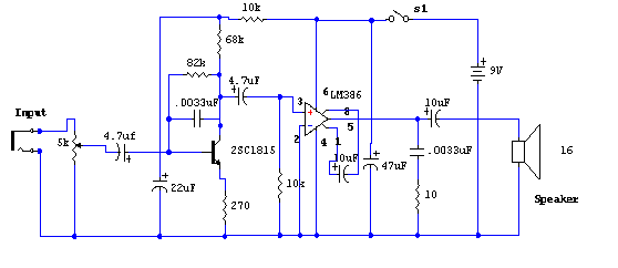
Signal Tracer
The primary component of this circuit is the LM386 amplifier chip. Additionally, it incorporates a transistor input to buffer the input signal and provide additional gain for the LM386.
The LM386 is a low-voltage audio power amplifier capable of delivering up...

Little dipper
The circuit consists of two fundamental components: the oscillator and the detector. The oscillator employs a Field Effect Transistor (FET) in a Colpitts configuration. The energy circulating within the oscillator's tank is coupled through capacitor C4 to the detector circuit,...

The Ecology of the Oscillator Transmitter
An oscillator-only transmitter appears to be the simplest way to access the radio airwaves; however, it presents several challenges as part of a transmitting and receiving station. The issue of finding an adequate crystal-controlled transmitter for newcomers wishing to operate...
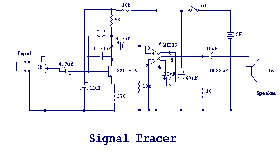
Simple LM386 amplifier
The main part of this circuit is the LM386 amplifier chip. It also uses a transistor input to buffer the input signal and provide extra gain for the LM386. The little unit has helped me out on numerous occasions when...

With a CD4011 dual-produced sound and light control delay lamp circuit
The main circuit utilizes a two-input NAND gate composed of four digital integrated circuits. This includes a NAND gate microphone amplifier circuit, a light control mechanism using an "AND gate," and a monostable delay control circuit formed by NAND gates...
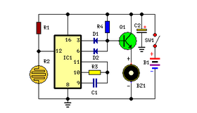
Fridge Door Alarm Circuit
Emits a beep if the door remains open for more than 20 seconds. This circuit is housed in a compact enclosure and is positioned in the refrigerator near the lamp or the opening.
The described circuit functions as a door alarm...

The oscillator and trigger circuit with operational amplifier
Figure a illustrates a multivibrator circuit capable of generating a square wave signal. Figure b depicts a flip-flop circuit that utilizes the falling edge of the input signal to produce a trigger pulse signal. Figure c represents a monostable circuit,...