


Car Alarm With Horn As Loudspeaker

Description: An auto horn operates as a speaker within a limited audio-frequency range. This circuit utilizes a 555 timer configured as an oscillator to drive an MJE34 transistor, which subsequently activates the horn. Normal horn operation is maintained through the use of a blocking diode, D4.
The described circuit employs a 555 timer in astable mode, which generates a square wave output. The frequency of the output can be adjusted by varying the resistors and capacitors connected to the timer. This output is fed into the base of the MJE34 transistor, which acts as a switch. When the timer outputs a high signal, the transistor is turned on, allowing current to flow from the power supply through the horn, causing it to produce sound.
The MJE34 transistor is chosen for its ability to handle higher currents, suitable for driving the horn. The use of a blocking diode, D4, serves to protect the circuit from back EMF generated by the inductive load of the horn when it is turned off. This diode ensures that the current flows in one direction, thus preventing damage to the 555 timer and the transistor.
To enhance the performance of this circuit, it is advisable to include a capacitor across the power supply terminals to filter out any noise and stabilize the voltage supply. Additionally, the frequency of the sound produced by the horn can be fine-tuned by adjusting the resistor-capacitor (RC) network connected to the 555 timer.
Overall, this circuit design effectively combines the functionalities of the 555 timer, a power transistor, and a blocking diode to create a reliable auto horn system. The simplicity of the design allows for easy implementation in automotive applications where audible alerts are necessary. An auto horn will work as a speaker of limited audio-frequency range. This circuit uses a 555 timer as a n oscillator to drive an MJE34 transistor, which in turn drives the horn. Normal horn operation is ensured by blocking diode D4.
The described circuit employs a 555 timer in astable mode, which generates a square wave output. The frequency of the output can be adjusted by varying the resistors and capacitors connected to the timer. This output is fed into the base of the MJE34 transistor, which acts as a switch. When the timer outputs a high signal, the transistor is turned on, allowing current to flow from the power supply through the horn, causing it to produce sound.
The MJE34 transistor is chosen for its ability to handle higher currents, suitable for driving the horn. The use of a blocking diode, D4, serves to protect the circuit from back EMF generated by the inductive load of the horn when it is turned off. This diode ensures that the current flows in one direction, thus preventing damage to the 555 timer and the transistor.
To enhance the performance of this circuit, it is advisable to include a capacitor across the power supply terminals to filter out any noise and stabilize the voltage supply. Additionally, the frequency of the sound produced by the horn can be fine-tuned by adjusting the resistor-capacitor (RC) network connected to the 555 timer.
Overall, this circuit design effectively combines the functionalities of the 555 timer, a power transistor, and a blocking diode to create a reliable auto horn system. The simplicity of the design allows for easy implementation in automotive applications where audible alerts are necessary. An auto horn will work as a speaker of limited audio-frequency range. This circuit uses a 555 timer as a n oscillator to drive an MJE34 transistor, which in turn drives the horn. Normal horn operation is ensured by blocking diode D4.
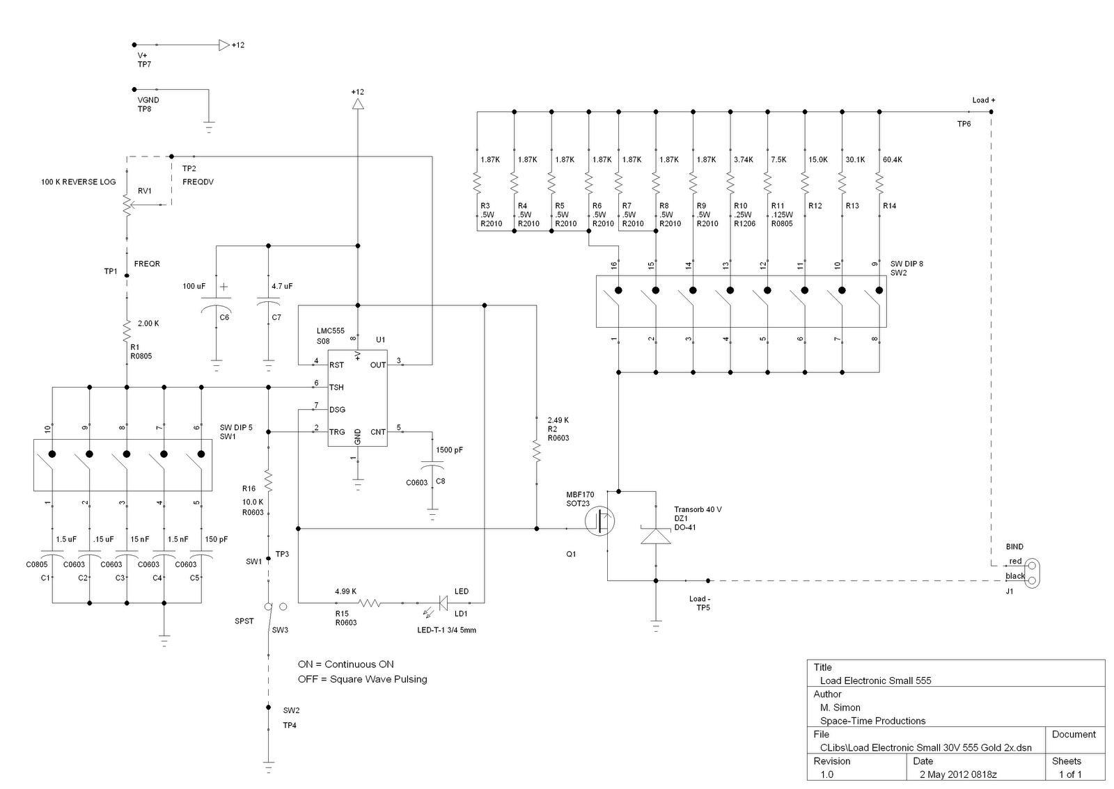
load electronic small 555
This is a license to use the files to manufacture up to 12 boards. If additional boards are required, please make contact. It is important to note that the order must specify the intent to produce 12 or fewer boards....

555 Fm Circuit Circuit
Circuit for applying a DC-coupled FM or PPM to a 555 configured as an oscillator. IC-1 is a Motorola MC-1374P, and IC-2 is a National LH0002C. L1 and L2 are Mouser Electronics #421IF200. C1 and C2 are silver mica capacitors...

Water Activated Alarm
The circuit utilizes a 555 timer configured as an astable oscillator and is powered by the emitter current of the BC109C transistor. In dry conditions, the transistor does not receive bias current and remains fully off. When the probes become...

Relay Timer Circuit With 555 Timer IC
This circuit includes a Relay Timer Circuit. One of the most commonly used circuits is that of the 555 Timer integrated circuit (IC). The circuit is designed to control a relay based on a timing interval.
The Relay Timer Circuit utilizing...

Electronic-voice-substitute
The 555 timer operates as a tone generator configured in astable mode. Its output at pin 3, which is a square wave, is converted into a triangle wave using resistor R1 and capacitor C2. The pitch of the generated voice...

Non-standard 555 Astable Multivibrator
A square wave generator with a variable frequency and a 50% duty cycle is required. While the 555 timer is a common choice, the standard astable multivibrator configuration alters the duty cycle when the frequency is adjusted. A circuit found...

Extending 555 Timers Delay with Integrator
The 555 IC is a widely used component for timer circuits. By incorporating an integrator circuit, it is possible to extend the timing period of the 555 IC timer while maintaining a reasonable capacitor size.
The 555 timer IC is a...

Auto-Arming Car Alarm circuit
The car alarm is a straightforward circuit with fundamental features that monitor all entry points of the vehicle, such as doors, using switches. It operates with a single switch (the arm switch) that allows the circuit to remain inactive until...

555 ultra-low frequency signal generator circuit diagram of a millivolt
The circuit depicted in the figure is a generator that includes an oscillator, a voltage follower, a zero amplitude adjustment, and a zero shift circuit. It is utilized as a self-balancing recorder for testing signals. The output signal ranges from...