


Compressor Protector
#compressor
#power-line
#AC voltage
#monitor
#power failure
#protection
#restoration
#safety
#voltage monitoring

Description: This circuit monitors the AC voltage of the power line. Upon a power failure, when power is restored, the circuit introduces a five-minute delay before energizing relay K1, which safeguards the compressor against low voltage conditions. U1 is a 16-stage counter with an integrated oscillator configured to divide by 8192. Resistors R7, R8, and capacitor C4 determine the oscillator frequency to approximately 25 Hz, resulting in a total counting interval of 300 seconds (5 minutes). After this interval, pin 8 of U1 goes high, forward-biasing transistor Q1, triggering SCR1, and activating relay K1. The circuit is capable of switching up to 30 A.
This circuit functions as a power-line voltage monitoring system, primarily designed to protect sensitive equipment, such as compressors, from potential damage due to low voltage conditions. The system operates by continuously monitoring the AC voltage levels and employing a timing mechanism to delay the reactivation of connected devices after a power interruption.
The core component of the circuit is U1, a 16-stage binary counter, which utilizes an internal oscillator to maintain accurate timing. The oscillator frequency is established by the combination of resistors R7 and R8, along with capacitor C4, which work together to create a frequency of approximately 25 Hz. This frequency is critical, as it directly influences the counting interval of the circuit, which is set to a total of 300 seconds (5 minutes).
When a power failure occurs, the circuit detects the absence of voltage and begins counting. After the power is restored, the 5-minute countdown commences. This delay is essential, as it allows time for the power supply to stabilize, thereby preventing potential damage to the compressor that could occur due to immediate re-energization under low voltage conditions.
Once the 5-minute delay has elapsed, pin 8 of U1 transitions to a high state, which activates Q1. As Q1 turns on, it provides the necessary forward bias to SCR1, enabling it to conduct. The conduction of SCR1 subsequently energizes relay K1, allowing it to switch on the connected load, which in this case is the compressor. The relay is designed to handle currents of up to 30 A, ensuring that it can manage the power requirements of the compressor effectively.
In summary, this circuit provides a robust solution for monitoring AC voltage and implementing a delay mechanism to protect equipment from low voltage scenarios, thereby enhancing the reliability and longevity of devices connected to the power line. This circuit monitors the power-line (ac) voltage. When a power failure occurs, on restoration of power, the circuit a dds a five-minute delay before energizing Kl, which protects the compressor against limited low voltage. Ul is a 16-stage counter with an integral oscillator that is set to divide by 8192. R7, R8, and C4 set the oscillator frequency to about 25 Hz, which produces a total count interval of 300 seconds (5 minutes).
After this time, pin 8 Ul goes high, which forward biases Ql, triggers SCR1, and activates Kl. Up to 30 A can be switched.
This circuit functions as a power-line voltage monitoring system, primarily designed to protect sensitive equipment, such as compressors, from potential damage due to low voltage conditions. The system operates by continuously monitoring the AC voltage levels and employing a timing mechanism to delay the reactivation of connected devices after a power interruption.
The core component of the circuit is U1, a 16-stage binary counter, which utilizes an internal oscillator to maintain accurate timing. The oscillator frequency is established by the combination of resistors R7 and R8, along with capacitor C4, which work together to create a frequency of approximately 25 Hz. This frequency is critical, as it directly influences the counting interval of the circuit, which is set to a total of 300 seconds (5 minutes).
When a power failure occurs, the circuit detects the absence of voltage and begins counting. After the power is restored, the 5-minute countdown commences. This delay is essential, as it allows time for the power supply to stabilize, thereby preventing potential damage to the compressor that could occur due to immediate re-energization under low voltage conditions.
Once the 5-minute delay has elapsed, pin 8 of U1 transitions to a high state, which activates Q1. As Q1 turns on, it provides the necessary forward bias to SCR1, enabling it to conduct. The conduction of SCR1 subsequently energizes relay K1, allowing it to switch on the connected load, which in this case is the compressor. The relay is designed to handle currents of up to 30 A, ensuring that it can manage the power requirements of the compressor effectively.
In summary, this circuit provides a robust solution for monitoring AC voltage and implementing a delay mechanism to protect equipment from low voltage scenarios, thereby enhancing the reliability and longevity of devices connected to the power line. This circuit monitors the power-line (ac) voltage. When a power failure occurs, on restoration of power, the circuit a dds a five-minute delay before energizing Kl, which protects the compressor against limited low voltage. Ul is a 16-stage counter with an integral oscillator that is set to divide by 8192. R7, R8, and C4 set the oscillator frequency to about 25 Hz, which produces a total count interval of 300 seconds (5 minutes).
After this time, pin 8 Ul goes high, which forward biases Ql, triggers SCR1, and activates Kl. Up to 30 A can be switched.

Compressor-Limiter-Clipper for FM transmitters
Audio signals as music or speech have big dynamic ranges. There are silent and loud sections. These audio signals aren't too good for a transmitter, which requires audio signal with constant level on the input. Limiter is a device, which...

Monitoring Voltages with Scaling Circuits
The UCD90124/A is utilized to monitor multiple voltages, some of which exceed 2.5V. Scaling circuits are implemented to prevent exceeding the 2.5V maximum on the MON inputs. The inquiry pertains to whether raw voltage values or scaled values should be...
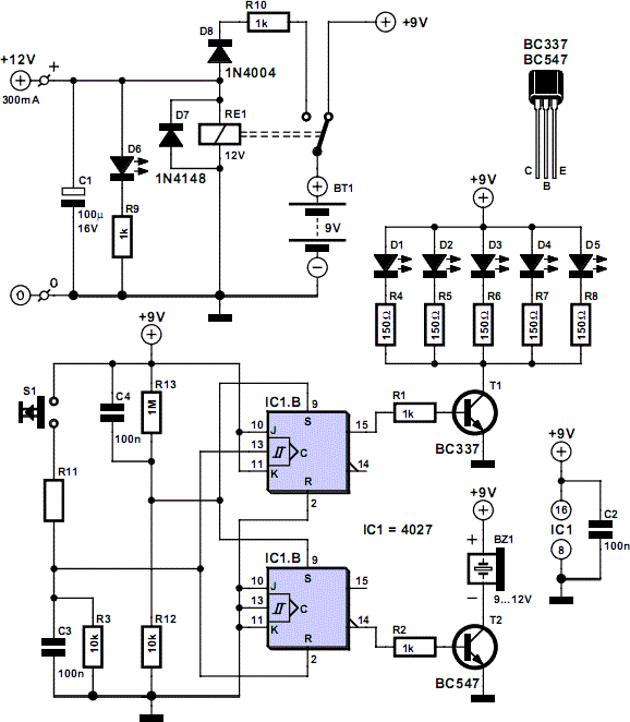
Mains Voltage Monitor
When the push button is pressed, a clock pulse appears on the CLK input of flip-flop IC1b. The output then toggles, causing the LEDs to turn off. Simultaneously, IC1a is reset, silencing the buzzer. Pressing the button again will turn...

Power failure detector
This circuit indicates that a power outage occurred for 1, 10, 100, and 500 seconds based on the values provided for R* and C*. After a power failure, the circuit can be reset by pressing the Reset button.
The described circuit...

Simple circuit shuts off system when supply voltage is low
When the supply voltage drops below a minimum threshold, it is often advisable to disconnect the supply from the system to prevent poor performance or erratic operation. The circuit presented achieves this with minimal cost, board space, and complexity. Additionally,...

Hi-ficompressor-with-pre-emphasis
The compressor includes a high-frequency pre-emphasis circuit (C2, R5, CS, R14) that addresses this issue. A corresponding de-emphasis circuit on the expander is necessary. More sophisticated designs may allow for variable pre-emphasis.
The compressor's high-frequency pre-emphasis circuit is crucial for enhancing...

Restoration project: Webster-Chicago 166-1
This is an old Webster-Chicago 166-1 amplifier that has been owned for several years, and a friend has volunteered to restore it.
The Webster-Chicago 166-1 amplifier is a vintage audio amplification device known for its robust construction and distinctive sound quality....

Variable-slope-compressor-expander
Compression and expansion ratios other than 2:1 can be achieved by the circuit shown. Rotation of the dual potentiometer causes the circuit connection to change from a basic compressor to a basic expander. At the center of rotation, the circuit...

monitor splitter
The signal sources in the analog output stage of the PC SVGA card are designed to present the correct impedance of 75 ohms on each line, utilizing five resistors. The input impedances of the transistors are sufficiently high to avoid...