


Dark detector circuit
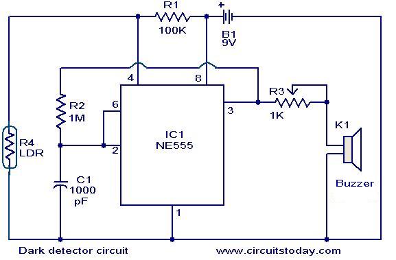
Description: The dark detector circuit illustrated here is designed to generate an audible alarm when the ambient light in a room is turned OFF. The circuit is constructed around the timer IC NE555. A general-purpose light-dependent resistor (LDR) is utilized for light sensing. When adequate light is present, the resistance of the LDR is significantly low. Conversely, in the absence of light, the resistance of the LDR increases. This change triggers the IC, which activates a buzzer to emit an alarm sound. Alternatively, if a transistor and relay are connected to the output (pin 3) of IC1 instead of the buzzer, electrical appliances can be controlled based on light levels.
The dark detector circuit employs the NE555 timer IC in its astable or monostable mode, depending on the desired application. The LDR serves as the primary sensing element, and its resistance varies inversely with the amount of light falling on it. This property allows the circuit to detect the transition from light to dark effectively.
In operation, when light levels drop below a predefined threshold, the LDR's resistance increases, causing a change in voltage at the input of the NE555. This change is detected by the timer, which then triggers the output pin (pin 3) to go high, activating the connected buzzer. The buzzer emits a sound, alerting occupants of the change in light conditions.
For applications requiring the control of electrical devices, a transistor can be used to amplify the signal from the NE555 output. This transistor can drive a relay, allowing for the switching on or off of various appliances based on the light detected by the LDR. The circuit can be further enhanced by incorporating adjustable resistors or potentiometers to fine-tune the sensitivity of the LDR, enabling customized operation based on specific lighting conditions.
The overall design is straightforward and can be implemented on a breadboard for prototyping or on a printed circuit board (PCB) for permanent installations. Proper power supply decoupling and component selection, including the buzzer type and relay specifications, are essential for ensuring reliable circuit performance.The dark detector circuit shown here can be used to produce an audible alarm when the light inside a room goes OFF. The circuit is build around timer IC NE555. A general purpose LDR is used for sensing the light. When proper light is falling on the LDR its resistance is very low. When there is no light the LDR resistance increases. At this time th e IC is triggered and drives the buzzer to produce an alarm sound. If a transistor and relay is connected at the output (pin3) of IC1 instead of the buzzer, electrical appliances can be switched according to the light.
The dark detector circuit employs the NE555 timer IC in its astable or monostable mode, depending on the desired application. The LDR serves as the primary sensing element, and its resistance varies inversely with the amount of light falling on it. This property allows the circuit to detect the transition from light to dark effectively.
In operation, when light levels drop below a predefined threshold, the LDR's resistance increases, causing a change in voltage at the input of the NE555. This change is detected by the timer, which then triggers the output pin (pin 3) to go high, activating the connected buzzer. The buzzer emits a sound, alerting occupants of the change in light conditions.
For applications requiring the control of electrical devices, a transistor can be used to amplify the signal from the NE555 output. This transistor can drive a relay, allowing for the switching on or off of various appliances based on the light detected by the LDR. The circuit can be further enhanced by incorporating adjustable resistors or potentiometers to fine-tune the sensitivity of the LDR, enabling customized operation based on specific lighting conditions.
The overall design is straightforward and can be implemented on a breadboard for prototyping or on a printed circuit board (PCB) for permanent installations. Proper power supply decoupling and component selection, including the buzzer type and relay specifications, are essential for ensuring reliable circuit performance.The dark detector circuit shown here can be used to produce an audible alarm when the light inside a room goes OFF. The circuit is build around timer IC NE555. A general purpose LDR is used for sensing the light. When proper light is falling on the LDR its resistance is very low. When there is no light the LDR resistance increases. At this time th e IC is triggered and drives the buzzer to produce an alarm sound. If a transistor and relay is connected at the output (pin3) of IC1 instead of the buzzer, electrical appliances can be switched according to the light.

Sun Light Chaser
With RFT illuminated, point R goes to 0 volt and LM runs. With LFT illuminated, point R goes to 0 volt and RM runs. With RFT and/or LFT not illuminated, points R/L go to +9 volt; P1 and P2 controls...
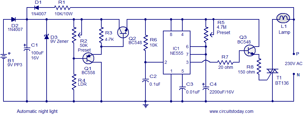
Automatic night light circuit that switches off after a preset time
A simple and inexpensive automatic night light circuit designed using the timer IC NE555, which extinguishes after a preset time. This time can also be adjusted.
The automatic night light circuit utilizes the NE555 timer IC configured in monostable mode. When...

Voltage doubler circuit using NE555
The circuit diagram of a simple voltage doubler using the NE555 timer is presented. In this configuration, the NE555 IC operates as an astable multivibrator at approximately 9 kHz. The bases of two transistors, Q1 and Q2, are connected together,...
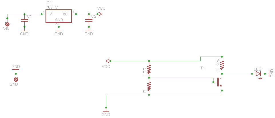
light sensor
When connecting this element in a voltage divider configuration, a high and low signal can be generated based on the amount of light detected by the sensor. An NPN transistor configured as an inverter further filters this signal to produce...

Basic Timer Control with NE555
Many friends take an interest in the circuit involving the highly popular IC 555, which is an integrated circuit. This circuit sets the time in a basic manner.
The IC 555 timer is a versatile and widely utilized component in electronics,...

Toggle on off switch
This circuit toggles on and off a NE555 with a single momentary switch. Unlike a mechanical bistable relay the circuit backs to the start condition if you switch off the power supply. No relay contact is used. This circuit could...

Light sensing circuit diagram
In the silicon-controlled trigger circuit, a cadmium sulfide cell is connected to a relaxation oscillator, which serves as a sensor to activate a blinking light in a darkroom. This setup causes a speaker to emit a warning sound of Ka,...

Fuse-Cum-Power Failure Indicator with alarm
The Fuse Cum Power Failure Indicator utilizes a thermistor and a timer IC (NE555) in its circuit design. The circuit diagram includes a parts list for the fuse cum power failure indicator, which signals instances of power failure.
The Fuse Cum...

Assembly of the F&DARC Square Wave Generator/Bridge
This project integrates multiple features into a compact unit. The core driver is based on an NE555 square wave generator. During development, the idea of building a square wave generator using discrete components was considered, but experiments revealed that the...