


darkness activated alarm
#555 timer
#LDR
#darkness sensor
#monostable
#alarm circuit
#light dependent resistor
#security
#trigger circuit
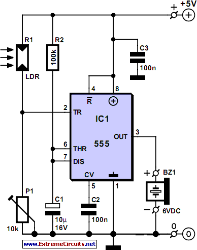
Description: Most darkness-activated alarms utilize operational amplifiers and various logic integrated circuits. This design presents a more cost-effective solution using the timeless 555 timer configured in monostable multivibrator mode. Components R2 and C1 form a timing network that produces a one-second delay. When the light-dependent resistor (LDR) is in darkness, its resistance increases, causing pin 2 of the 555 timer to be pulled to ground. This action triggers the monostable configuration, activating a 6-volt piezo buzzer. The preset resistor P1 is adjusted according to the ambient light levels. The circuit can be installed on a wall in a home. Once P1 is calibrated for the current ambient light, any shadow cast by an individual entering the room or hallway will activate the alarm.
The circuit operates on the principle of detecting changes in light intensity using an LDR, which is a variable resistor that decreases its resistance when exposed to light. In this configuration, the LDR is positioned in such a way that it remains in darkness when the area is unoccupied. The 555 timer, configured as a monostable multivibrator, is triggered when the LDR's resistance is sufficiently high, pulling the voltage at pin 2 low. This low voltage activates the timer, which then outputs a high signal at pin 3 for a predetermined duration, set by the values of R2 and C1.
The timing components, R2 and C1, are crucial for determining how long the buzzer will sound after the alarm is triggered. By selecting appropriate values for these components, one can adjust the duration of the alarm to suit specific requirements. The piezo buzzer, which operates at 6 volts, produces an audible sound when activated, alerting occupants of the presence of an intruder or unexpected movement.
The adjustable preset resistor P1 allows for fine-tuning of the circuit's sensitivity to ambient light conditions. This feature ensures that the alarm will only activate in low-light situations, preventing false alarms during the day or in well-lit environments. Installation on a wall is straightforward, and the compact nature of the circuit allows for easy integration into home security systems.
Overall, this circuit provides an efficient and economical solution for creating a darkness-activated alarm system, leveraging the reliability of the 555 timer and the simplicity of passive components. Proper calibration and placement will enhance its effectiveness in detecting motion in dimly lit areas.Most darkness activated alarms employ opamps and some logic ICs. Here, a less expensive approach is shown based on the eternal 555, this time in monostable multivibrator mode. Components R2 and C1 represent a one-second network. When the LDR (light dependent resistor) is in the dark, its resistance is high, pulling pin 2 of the 555 to ground.
This triggers the monostable and the (active!) 6-volt piezo buzzer will sound. Preset P1 is adjusted depending on ambient light levels. The circuit may be fitted on a wall in your home. Assuming P1 has been set for the existing ambient light level, the shadow cast by anybody entering the room or hallway will trigger the alarm.
The circuit operates on the principle of detecting changes in light intensity using an LDR, which is a variable resistor that decreases its resistance when exposed to light. In this configuration, the LDR is positioned in such a way that it remains in darkness when the area is unoccupied. The 555 timer, configured as a monostable multivibrator, is triggered when the LDR's resistance is sufficiently high, pulling the voltage at pin 2 low. This low voltage activates the timer, which then outputs a high signal at pin 3 for a predetermined duration, set by the values of R2 and C1.
The timing components, R2 and C1, are crucial for determining how long the buzzer will sound after the alarm is triggered. By selecting appropriate values for these components, one can adjust the duration of the alarm to suit specific requirements. The piezo buzzer, which operates at 6 volts, produces an audible sound when activated, alerting occupants of the presence of an intruder or unexpected movement.
The adjustable preset resistor P1 allows for fine-tuning of the circuit's sensitivity to ambient light conditions. This feature ensures that the alarm will only activate in low-light situations, preventing false alarms during the day or in well-lit environments. Installation on a wall is straightforward, and the compact nature of the circuit allows for easy integration into home security systems.
Overall, this circuit provides an efficient and economical solution for creating a darkness-activated alarm system, leveraging the reliability of the 555 timer and the simplicity of passive components. Proper calibration and placement will enhance its effectiveness in detecting motion in dimly lit areas.Most darkness activated alarms employ opamps and some logic ICs. Here, a less expensive approach is shown based on the eternal 555, this time in monostable multivibrator mode. Components R2 and C1 represent a one-second network. When the LDR (light dependent resistor) is in the dark, its resistance is high, pulling pin 2 of the 555 to ground.
This triggers the monostable and the (active!) 6-volt piezo buzzer will sound. Preset P1 is adjusted depending on ambient light levels. The circuit may be fitted on a wall in your home. Assuming P1 has been set for the existing ambient light level, the shadow cast by anybody entering the room or hallway will trigger the alarm.

Light/dark relay switch
This kit is the most basic, practical circuit to build using an LDR to turn on a relay. The two transistors connected as a Darlington pair give the circuit enough sensitivity, while the trimpot gives sensitivity adjustment. The switching point...

Rf driver audio oscillator circuit diagram
As shown in the figure, the 555 timer, resistors R1, RP1, and capacitor C1 form a controlled audio oscillator. The frequency of the oscillator is given by the formula f = 1.44 / ((R1 + 2 * RP1) * C1)....

555 camera flash delay circuit
As shown in figure 17-1, the camera flash delay circuit is designed to capture high-speed scenes, allowing for very short exposure times. The light gate consists of a luminous diode and a 3DU type photosensitive tube. When the light is...

Smoke detector using 555 timer circuit
This smoke detector utilizes a 555 timer circuit along with common electronic components. The photo interrupter module serves as the smoke detection element, while the 555 timer is configured in astable mode to function as an audio frequency oscillator, which...

555 monostable circuit trigger solenoid
A circuit is being designed to trigger solenoid valves for airbags in a car, requiring a time range of 0 to 1 second. The selected valves operate at 12V, 0.5A, and can activate within a maximum speed of 200 milliseconds....

555 Electronic Metronome Circuit
The metronome circuit has been assembled multiple times without success. Two manufacturers of the 555 timer, ON Semiconductor and National Semiconductor, provide circuit designs that differ from the original. In their designs, pins 2, 6, and 7 are not connected...

Courtesy-light-extender
The circuit maintains the courtesy light's illumination for 30 seconds after the door is closed. The lead from the door switch is disconnected and linked to the 555 timer circuit. The 555 timer is configured in monostable mode and is...
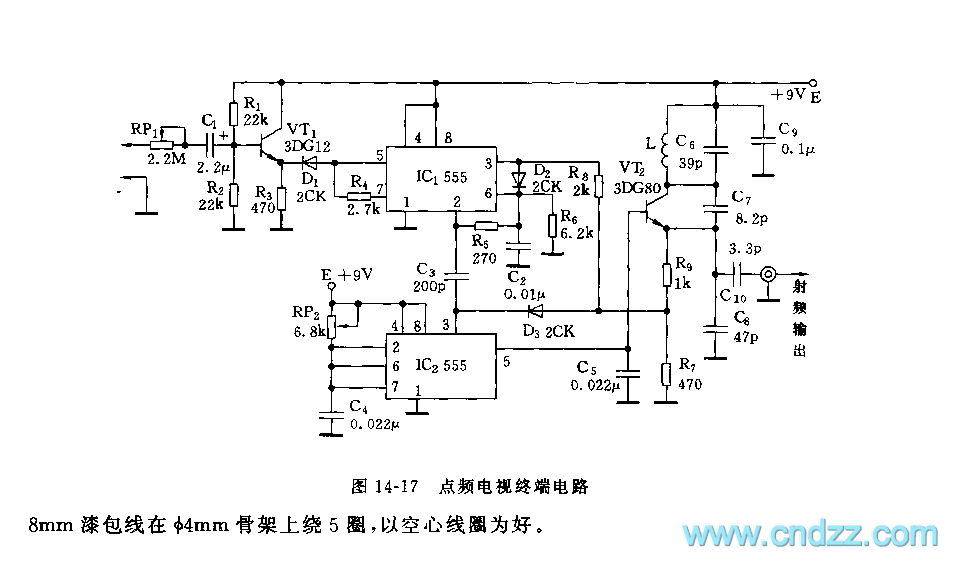
555 point-frequency TV terminal circuit
As shown in figure 14-17, this circuit consists of the input circuit, the line frequency synchronization generator, the sample-and-hold circuit, the voltage control delay generator, and the RF modulator. The input circuit includes the input attenuator RP1 and the emitter...

A Repeating Timer Circuit No.7
This timer utilizes a basic monostable circuit. The duration for which the relay remains energized, referred to as the ON period, is regulated by the resistor R3 and capacitor C2. Conversely, the duration for which the relay remains de-energized, known...