


DIGITAL LOCK CIRCUIT
#digital lock
#security
#relay
#sequence code
#reset circuit
#access control
#electronics
#C3 timing
#Q2 transistor

Description: This circuit relies on the input of a correct sequence code. An incorrect number that is not part of the code triggers a reset of the circuit. When the correct code is entered, Q2 activates relay K1 for a brief period, determined by capacitor C3.
The circuit functions as a basic code entry system, utilizing a combination of digital logic and analog components to ensure that only a specific sequence of inputs can trigger the relay operation. The primary components include a microcontroller or a simple logic gate arrangement to evaluate the entered code, a transistor (Q2) to switch the relay, and a timing capacitor (C3) that defines the duration of the relay activation.
Upon entering a sequence, the system checks each digit against a predefined code stored in memory. If an incorrect digit is detected, the circuit resets, ensuring that no unauthorized access is granted. This reset mechanism can be implemented using a flip-flop or a simple reset line that is activated by the incorrect input.
When the correct sequence is entered, Q2 is triggered, allowing current to flow through relay K1. The relay then closes its contacts, which can be used to control various external devices, such as alarms, locks, or indicators. The duration of this activation is governed by the charge time of capacitor C3, which can be calculated based on the RC time constant, where the resistance in the circuit and the capacitance determine how long the relay remains activated before returning to its default state.
The design of this circuit can be further enhanced by incorporating features such as debounce logic for the input keys to prevent false triggering, as well as visual indicators (LEDs) to provide feedback on the status of the code entry process. Additionally, the circuit could be expanded with security features, such as a lockout period after multiple incorrect attempts, to increase its robustness against unauthorized access attempts.This circuit depends on the entry of a correct sequence code. An incorrect number that is not part of the code causes the circuit to reset. When the correct code is entered, Q2 operates relay K1 for a short time, depending on C3.
The circuit functions as a basic code entry system, utilizing a combination of digital logic and analog components to ensure that only a specific sequence of inputs can trigger the relay operation. The primary components include a microcontroller or a simple logic gate arrangement to evaluate the entered code, a transistor (Q2) to switch the relay, and a timing capacitor (C3) that defines the duration of the relay activation.
Upon entering a sequence, the system checks each digit against a predefined code stored in memory. If an incorrect digit is detected, the circuit resets, ensuring that no unauthorized access is granted. This reset mechanism can be implemented using a flip-flop or a simple reset line that is activated by the incorrect input.
When the correct sequence is entered, Q2 is triggered, allowing current to flow through relay K1. The relay then closes its contacts, which can be used to control various external devices, such as alarms, locks, or indicators. The duration of this activation is governed by the charge time of capacitor C3, which can be calculated based on the RC time constant, where the resistance in the circuit and the capacitance determine how long the relay remains activated before returning to its default state.
The design of this circuit can be further enhanced by incorporating features such as debounce logic for the input keys to prevent false triggering, as well as visual indicators (LEDs) to provide feedback on the status of the code entry process. Additionally, the circuit could be expanded with security features, such as a lockout period after multiple incorrect attempts, to increase its robustness against unauthorized access attempts.This circuit depends on the entry of a correct sequence code. An incorrect number that is not part of the code causes the circuit to reset. When the correct code is entered, Q2 operates relay K1 for a short time, depending on C3.

R/C On/Off Motor Controller with Brake
A relay-based on/off controller on the other hand can be very efficient. A typical relay has a contact resistance of 3 milliOhm. At 20A, this translates to a voltage drop of 0.06 volts, with a power loss of 1.2W. The...

DC relay circuits to delay the release of a second
The circuit depicted in Figure 6-24 includes a relay coil with both ends connected in parallel to either a resistor Rf or an auxiliary diode VD. This configuration is equivalent to providing power after a short circuit, which increases the...

Digital Code Lock
Digital code lock designed with effective hacking prevention against brute force attacks. The standard user lock consists of 5 digits, while the master lock features 10 digits, making it challenging to compromise. This project is associated with the creation of...

Relay protection circuit
Operating power protection devices can be categorized into two types: DC power supply operation and AC operation. AC operating power is favored due to its lower investment costs, simpler operation, and reliable secondary circuit maintenance, making it widely used in...
relay In a circuit being switched by an NPN transistor do power supply and input need the same ground
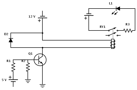
Create a circuit that enables the activation of a relay to control an LED. The relay operates at 12 V, while the available input voltage is 5 V. An NPN transistor will be utilized to switch the power to the...

Controlling a relay with a digital logic level circuit
The schematic below illustrates four methods of controlling a relay with a digital logic signal. Figure A can be used in most cases where the relay coil requires 100 mA or less and the input current is 2 milliamps or...

JB-22 transistor relay circuit
When the input is disconnected, the transistor VTi conducts, while VTz is in cutoff, causing relay KA to release. When the input is shorted, VTi is cut off, VTz conducts, and relay KA is activated.
In this circuit configuration, the operation...

Digital Entry Lock Circuit
A block pinout diagram of the LS7220 keyless-lock IC is presented. The keypad must provide each key with a contact to a common connection. In this instance, the common connection is linked to the positive supply rail, allowing a positive...

Four reversing operation of the reverse brake circuit
The circuit depicted in Figure 3-131 utilizes a relay instead of a speed control relay. It is designed to operate effectively in dusty environments and other challenging conditions.
The circuit operates by employing a relay as a primary switching mechanism, which...