


Economy radar detectors
#radar detector
#op-amp
#piezo transducer
#signal detection
#security system
#1458 dual op-amp
#current-to-voltage converter
#threshold adjustment

Description: This circuit utilizes a 1458 dual operational amplifier (op-amp) to create a radar detector. Capacitor C1 serves as the radar signal detector. The first op-amp functions as a current-to-voltage converter, while the second op-amp buffers the output to drive a piezo transducer. Resistor R5 determines the switching threshold of the second op-amp; it is typically adjusted to ensure that the circuit only triggers on background noise and is then slightly backed off. The circuit's response can be fine-tuned by adjusting the length of the leads on C1. For standard road-radar systems, the input capacitor's leads should measure approximately 0.5 to 0.6 inches in length.
The described radar detector circuit employs a 1458 dual op-amp, which consists of two independent, high-gain, frequency-compensated op-amps. The design leverages the first op-amp to convert the radar signal detected by capacitor C1 into a voltage signal. This conversion is essential for accurately detecting the presence of radar signals. The output from the first op-amp is then fed into the second op-amp, which acts as a buffer. This buffering is crucial as it isolates the detection circuitry from the load imposed by the piezo transducer, ensuring that the op-amp operates within its optimal range and maintains signal integrity.
Resistor R5 plays a pivotal role in setting the threshold at which the second op-amp activates the piezo transducer. By adjusting R5, the sensitivity of the circuit can be fine-tuned to avoid false triggers from background noise, allowing the detector to respond only to significant radar signals. This adjustment is vital for practical applications, as it enhances the reliability of the radar detection.
The tuning of the circuit's response can also be influenced by the physical characteristics of capacitor C1. Specifically, the length of the leads connected to C1 can affect the circuit's sensitivity and response time. For optimal performance with typical road-radar systems, the recommended lead length of 0.5 to 0.6 inches is critical. This specification is based on empirical testing and ensures that the radar detector performs effectively in real-world scenarios.
Overall, this radar detector circuit exemplifies a balance of simple design and effective performance, making it suitable for various applications where radar detection is necessary.This circuit uses a 1458 dual op-amp to form a radar detector. C1 is the detector of the radar signal. The first op-amp forms a current-to-voltage converter and the second op-amp buffers the output to drive the piezo transducer. R5 sets the switching threshold of the second op-amp; normally it is adjusted so that the circuit barely triggers on bac
kground noise, then it`s backed off a bit. The response of the circuit may be tuned by adjusting the length of the leads on C1. For typical road-radar systems, the input capacitor`s leads should be about 0. 5 to 0. 6 inches long.
The described radar detector circuit employs a 1458 dual op-amp, which consists of two independent, high-gain, frequency-compensated op-amps. The design leverages the first op-amp to convert the radar signal detected by capacitor C1 into a voltage signal. This conversion is essential for accurately detecting the presence of radar signals. The output from the first op-amp is then fed into the second op-amp, which acts as a buffer. This buffering is crucial as it isolates the detection circuitry from the load imposed by the piezo transducer, ensuring that the op-amp operates within its optimal range and maintains signal integrity.
Resistor R5 plays a pivotal role in setting the threshold at which the second op-amp activates the piezo transducer. By adjusting R5, the sensitivity of the circuit can be fine-tuned to avoid false triggers from background noise, allowing the detector to respond only to significant radar signals. This adjustment is vital for practical applications, as it enhances the reliability of the radar detection.
The tuning of the circuit's response can also be influenced by the physical characteristics of capacitor C1. Specifically, the length of the leads connected to C1 can affect the circuit's sensitivity and response time. For optimal performance with typical road-radar systems, the recommended lead length of 0.5 to 0.6 inches is critical. This specification is based on empirical testing and ensures that the radar detector performs effectively in real-world scenarios.
Overall, this radar detector circuit exemplifies a balance of simple design and effective performance, making it suitable for various applications where radar detection is necessary.This circuit uses a 1458 dual op-amp to form a radar detector. C1 is the detector of the radar signal. The first op-amp forms a current-to-voltage converter and the second op-amp buffers the output to drive the piezo transducer. R5 sets the switching threshold of the second op-amp; normally it is adjusted so that the circuit barely triggers on bac
kground noise, then it`s backed off a bit. The response of the circuit may be tuned by adjusting the length of the leads on C1. For typical road-radar systems, the input capacitor`s leads should be about 0. 5 to 0. 6 inches long.
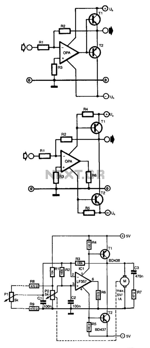
Op Amp Power Driver
Frequently, the output current of an operational amplifier is inadequate for applications such as driving a small motor or loudspeaker. This issue is typically resolved by adding an emitter follower to the circuit. However, this configuration does not allow the...

Single Capacitor Powers Audio Mixer
Micropower and low-voltage operational amplifiers enable the construction of high-performance analog signal processors that do not require batteries or wall transformers. Instead, a capacitor can serve as the power source. The circuit illustrated in Figure 1 depicts an analog mixer...
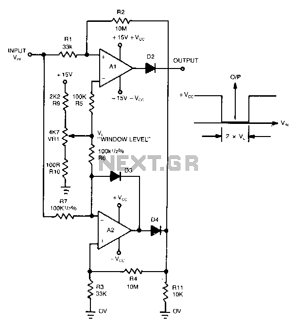
Window-detector
This novel window detector utilizes only two operational amplifiers. The width of the window can be adjusted using a 4.7 kΩ potentiometer.
The described window detector circuit employs two operational amplifiers (op-amps) to create a functional and efficient signal conditioning system....

Audio Signal Clipping Indicator
A window comparator formed by two operational amplifiers packaged into IC1 is the heart of the circuit below. With this technique, we can detect precisely and symmetrically.
The window comparator circuit utilizes two operational amplifiers (op-amps) configured to create a defined...
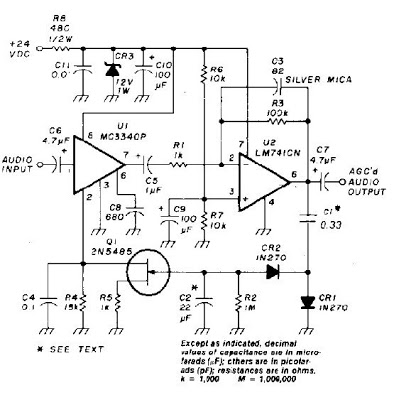
Auto gain Control op-ampCircuit
An audio signal applied to VI is passed through the operational amplifier 741, U2. After being amplified, the output signal V2 is sampled and applied to a negative voltage doubler/rectifier circuit composed of diodes CR1 and CR2, along with capacitor...

Capacitor Allows Higher Slew Rates
In this circuit, a Burr-Brown operational amplifier provides a slew rate of 135 V/μs. The inclusion of capacitor C2 reduces the high-frequency feedback factor to less than unity, enabling higher slew-rate amplifiers to be compensated for gains greater than one.
This...

1Mhz-meter-driver-amplifier
This circuit utilizes the CA3100 BiMOS operational amplifier to drive a 1-mA meter movement to its full scale with a 1-V RMS input.
The circuit configuration incorporates the CA3100 BiMOS operational amplifier, which is known for its high input impedance and...

Inverting Summing Amplifier Circuit
The output of Ul is the sum of Vv, multiplied by the ratio of Rx to Rv, RJRV, and respectively. Resistors R1, R2, and R3 are selected as required for individual gains. Additionally, R4 influences the gain of all these...

Circuit examples
Input J4 features an offset function that is activated only when no plug is inserted into J4, as the switching contact of J4 connects to the positive supply voltage through the protection resistor R8. The inverting sum of all inputs...