


Electronic Door Release circuit
#door release
#relay
#security
#access control
#battery powered
#code entry
#timer
#electronic lock
#home automation

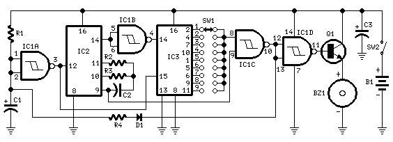
Description: This circuit is designed to operate an electrical door-release mechanism, but it can also be utilized for other applications. When the user enters a four-digit code of their choice, the relay will energize for a preset time period. The relay contacts are used to power the release mechanism. The standby current is nearly zero, making battery power a feasible option.
The circuit primarily consists of a microcontroller, a keypad, a relay module, and a power supply. The microcontroller serves as the brain of the system, processing the input from the keypad and controlling the relay based on the entered code. The keypad allows the user to input a four-digit code, which is compared against a stored value in the microcontroller's memory.
When the correct code is entered, the microcontroller sends a signal to the relay module to energize it. This action closes the relay contacts, allowing current to flow to the door-release mechanism, which could be an electronic lock or similar device. The relay is configured to remain energized for a predetermined time, which can be adjusted based on the requirements of the application. After this time period, the relay will deactivate, cutting power to the release mechanism.
The circuit is designed with power efficiency in mind. The standby current is kept to a minimum, allowing the system to be powered by batteries for extended periods without significant drain. This feature makes it suitable for remote installations or situations where access to mains power is limited.
In addition to the primary door-release function, this circuit can be adapted for various applications, such as remote access control for gates, alarm systems, or any device requiring secure electronic access. The versatility of the design allows for easy modifications to accommodate different user requirements, such as changing the code or adjusting the relay timing. Overall, this circuit provides a reliable and efficient solution for electronic access control.This circuit is designed to operate an electrical door-release mechanism - but it will have other applications. When you enter the four-digit code of your choice - the relay will energize for a preset time period.
Use the relay contacts to power the release mechanism. The standby current is virtually zero - so battery power is a realistic option..
The circuit primarily consists of a microcontroller, a keypad, a relay module, and a power supply. The microcontroller serves as the brain of the system, processing the input from the keypad and controlling the relay based on the entered code. The keypad allows the user to input a four-digit code, which is compared against a stored value in the microcontroller's memory.
When the correct code is entered, the microcontroller sends a signal to the relay module to energize it. This action closes the relay contacts, allowing current to flow to the door-release mechanism, which could be an electronic lock or similar device. The relay is configured to remain energized for a predetermined time, which can be adjusted based on the requirements of the application. After this time period, the relay will deactivate, cutting power to the release mechanism.
The circuit is designed with power efficiency in mind. The standby current is kept to a minimum, allowing the system to be powered by batteries for extended periods without significant drain. This feature makes it suitable for remote installations or situations where access to mains power is limited.
In addition to the primary door-release function, this circuit can be adapted for various applications, such as remote access control for gates, alarm systems, or any device requiring secure electronic access. The versatility of the design allows for easy modifications to accommodate different user requirements, such as changing the code or adjusting the relay timing. Overall, this circuit provides a reliable and efficient solution for electronic access control.This circuit is designed to operate an electrical door-release mechanism - but it will have other applications. When you enter the four-digit code of your choice - the relay will energize for a preset time period.
Use the relay contacts to power the release mechanism. The standby current is virtually zero - so battery power is a realistic option..

Up/Down Timer For A Power Antenna
This up/down timer was designed to control a power antenna on a late-model vehicle. Normally, this vehicle uses a body computer to control the antenna. However, the owner intended to install a high-powered audio stereo system. The original stereo system...

APPLIANCE CONTROL USING TIMER - PROJECT
This document presents an electronic project focused on device control using a timer. This circuit allows for the activation of an appliance at a specified time for a predetermined duration. It can be applied to manage the operation of systems...
jogging timer circuit diagram
This circuit was developed in response to requests from website visitors for a timer that can emit a beep after intervals of one, two, three minutes, and so forth, for jogging purposes. As depicted in the circuit diagram, SW1 is...

A Tan Timer Circuit
This timer is designed for individuals seeking to achieve a tan while minimizing excessive exposure to sunlight. A rotary switch allows the user to set the timer based on six classified photo-types. A photoresistor adjusts the preset time value in...

Dark and Light Activated Relay
The potentiometer adjusts the trigger level. The diode in the circuit diagram is specified as 1N914, which is suitable for light-duty relays; however, since the 1N914 is a signal diode, it is not ideal. A 1N4001 or a better alternative...

relay interfacing with coolrunner ii cpld
The CoolRunner-II board features external 5V relay interfacing, as indicated in the accompanying figure. The ULN2803 is utilized as a driver for the CPLD I/O lines, with the driver outputs connected to the relay modules. A PTB connector is provided...

Electromechanical relay logic
In ladder logic symbolism, an electromechanical relay coil is depicted as a circle, while the contact(s) actuated by the coil are represented by two parallel lines, resembling a capacitor symbol. To interpret a ladder logic diagram, it is essential to...

R/C On/Off Motor Controller with Brake
A relay-based on/off controller on the other hand can be very efficient. A typical relay has a contact resistance of 3 milliOhm. At 20A, this translates to a voltage drop of 0.06 volts, with a power loss of 1.2W. The...

Power-Off Time Delay Relay circuit
The two circuits demonstrate the process of opening a relay contact shortly after the ignition or light switch is turned off. The capacitor is charged, and the relay remains closed until the voltage at the diode anode reaches +12 volts.
The...