


Fridge Alarm with 4060
#fridge alarm
#4060 IC
#photo resistor
#sensor
#home automation
#security
#light detection
#circuit design
#electronics
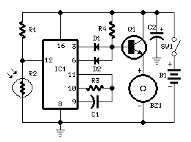
Description: This circuit, enclosed into a small box, is placed in the fridge near the lamp (if any) or the opening. With the door closed the interior of the fridge is in the dark, the photo resistor R2 presents a high resistance (>200K) thus clamping IC1 by holding pin 12 high. When a beam of light enters from the opening, or the fridge lamp illuminates, the photo resistor lowers its resistance (<2K), pin 12 goes low, IC1 starts counting and, after a preset delay (20 seconds in this case) the piezo sounder beeps for 20 sec.
The described circuit functions as a light-activated timer and alarm system specifically designed for installation within a refrigerator. The core components include a photoresistor (R2), an integrated circuit (IC1), and a piezo sounder, all housed within a compact enclosure.
When the refrigerator door is closed, the internal environment remains dark. Under these conditions, the photoresistor R2 exhibits a high resistance, exceeding 200kΩ. This high resistance prevents current flow through R2, thereby keeping pin 12 of IC1 in a high state. Consequently, IC1 remains inactive, ensuring that the piezo sounder does not emit any sound.
Upon opening the refrigerator door, ambient light enters the compartment, causing the resistance of R2 to drop significantly, falling below 2kΩ. This change in resistance allows current to pass through R2, which pulls pin 12 of IC1 low. The transition from high to low triggers IC1 to commence its timing sequence.
IC1 is configured to count for a predetermined duration, which is set to 20 seconds in this application. After this interval elapses, IC1 activates the piezo sounder. The sounder emits a series of beeps lasting for 20 seconds, serving as an auditory alert. This feature is particularly beneficial for preventing the refrigerator door from being inadvertently left open, which could lead to energy loss and spoilage of food items.
Additional considerations for this circuit design include the selection of the photoresistor, which should be sensitive enough to detect typical indoor lighting conditions, and the choice of IC1 to ensure that it has the necessary timing capabilities and output drive strength to activate the piezo sounder effectively. Power supply requirements should also be taken into account to ensure reliable operation within the refrigerator environment.This circuit, enclosed into a small box, is placed in the fridge near the lamp (if any) or the opening. With the door closed the interior of the fridge is in the dark, the photo resistor R2 presents a high resistance (>200K) thus clamping IC1 by holding pin 12 high.
When a beam of light enters from the opening, or the fridge lamp illuminates, the photo resistor lowers its resistance (<2K), pin 12 goes low, IC1 starts counting and, after a preset delay (20 seconds in this case) the piezo sounder beeps for 20 sec. t
The described circuit functions as a light-activated timer and alarm system specifically designed for installation within a refrigerator. The core components include a photoresistor (R2), an integrated circuit (IC1), and a piezo sounder, all housed within a compact enclosure.
When the refrigerator door is closed, the internal environment remains dark. Under these conditions, the photoresistor R2 exhibits a high resistance, exceeding 200kΩ. This high resistance prevents current flow through R2, thereby keeping pin 12 of IC1 in a high state. Consequently, IC1 remains inactive, ensuring that the piezo sounder does not emit any sound.
Upon opening the refrigerator door, ambient light enters the compartment, causing the resistance of R2 to drop significantly, falling below 2kΩ. This change in resistance allows current to pass through R2, which pulls pin 12 of IC1 low. The transition from high to low triggers IC1 to commence its timing sequence.
IC1 is configured to count for a predetermined duration, which is set to 20 seconds in this application. After this interval elapses, IC1 activates the piezo sounder. The sounder emits a series of beeps lasting for 20 seconds, serving as an auditory alert. This feature is particularly beneficial for preventing the refrigerator door from being inadvertently left open, which could lead to energy loss and spoilage of food items.
Additional considerations for this circuit design include the selection of the photoresistor, which should be sensitive enough to detect typical indoor lighting conditions, and the choice of IC1 to ensure that it has the necessary timing capabilities and output drive strength to activate the piezo sounder effectively. Power supply requirements should also be taken into account to ensure reliable operation within the refrigerator environment.This circuit, enclosed into a small box, is placed in the fridge near the lamp (if any) or the opening. With the door closed the interior of the fridge is in the dark, the photo resistor R2 presents a high resistance (>200K) thus clamping IC1 by holding pin 12 high.
When a beam of light enters from the opening, or the fridge lamp illuminates, the photo resistor lowers its resistance (<2K), pin 12 goes low, IC1 starts counting and, after a preset delay (20 seconds in this case) the piezo sounder beeps for 20 sec. t

Visible and Infrared Light Detectors
The sensors used are silicon phototransistors and Cadmium Sulfide (CdS) photocells. Both of these sensors allow less current to flow when they are dark than when lighted. Phototransistors change their conductance while photocells change their resistance depending on the intensity...

Sensor-Activated Relay Pulser Circuit
A sensor activates transistor Q1 to turn on the low-frequency 555 oscillator, which generates pulses to control LAMP II. The sensor may respond to variations in light or temperature. Either resistor RA or RB can function as the sensor, depending...
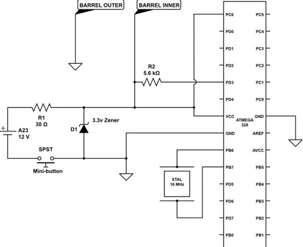
electronic hotel door vulnerability using stealth lock circuit
The term "pentester" refers to a penetration tester, individuals who assess security vulnerabilities. Many high-end hotels globally depend on keycard locks for securing hotel rooms. However, recent incidents of theft have shown that these locks may not be as secure...
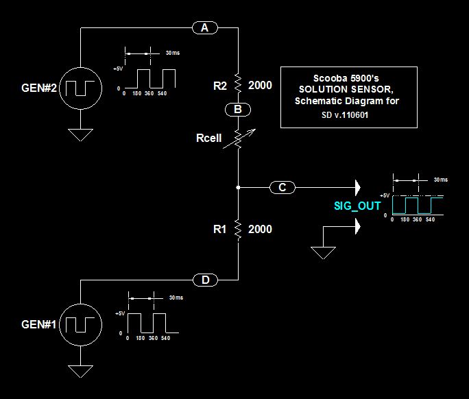
Scoobas Solution Sensing Tactic
This document serves multiple purposes, primarily to document the methods employed by a Scooba robot to detect: a) the presence of an acceptable cleaning solution being delivered to its pump, and b) the excess presence of used solution collected off...

case stepper
Beige Bag Software has been offering affordable and innovative circuit design tools since 1990. B2 Spice provides schematics as well as analog, digital, and mixed-mode electronic circuit simulation. It integrates with EAGLE and CADSTAR PCB software.
B2 Spice is a powerful...
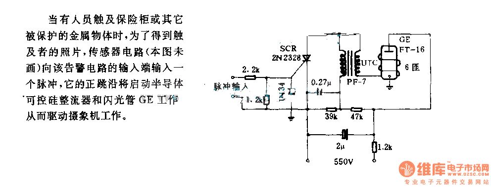
The alarm circuit diagram for safety box and other metal objects
When an individual touches the safety box or other protected metal objects, the sensor circuit generates a pulse to the alarm circuit. The positive edge of this pulse activates the semiconductor and thyristor flash GE, subsequently triggering the camera to...
Visible and Infrared Light Detectors
The sensors used are silicon phototransistors and Cadmium Sulfide (CdS) photocells. Both of these sensors allow less current to flow when they are dark than when lighted. Phototransistors change their conductance while photocells change their resistance depending on the intensity...

Adjustable light detection switch
R2 sets the circuit's threshold. When the light intensity at the PCI's surface decreases, the resistance of PCI, a cadmium-sulfide photo-resistor, increases. This results in a decrease in voltage at the inverting input of the 741 operational amplifier. When the...

Fridge Door Alarm Schematic 2nd Version
The main purpose of this design is to address a minor flaw in the widely used Fridge Door Alarm circuit, which has been available on this website since 1999 and has been constructed by many hobbyists. This circuit ceases to...