


Latching burglar alarm II

Description: Closing the protective circuit (R1 to R2) applies positive voltage to the gate of SCR1 and activates the alarm. It can only be turned off with SI.
The described circuit utilizes a Silicon Controlled Rectifier (SCR) as a key component for alarm activation. When the protective circuit, represented by resistors R1 and R2, is closed, it allows a positive voltage to be applied to the gate terminal of SCR1. This action triggers the SCR, allowing current to flow through its anode to cathode, thereby energizing the alarm system.
Resistors R1 and R2 are crucial in setting the appropriate gate voltage for SCR1. The values of these resistors can be selected based on the required gate current to ensure reliable triggering of the SCR. The alarm system, which could be a piezo buzzer or an LED indicator, is connected in series with the SCR, ensuring that the alarm is activated only when the SCR is conducting.
The circuit also includes a switch, labeled SI, which serves as the control mechanism for deactivating the alarm. When SI is opened, it interrupts the current flow to the gate of SCR1, allowing the SCR to turn off only when the current through it drops below its holding current. This design ensures that the alarm remains active until SI is manually disengaged, providing a reliable means of alerting users to potential hazards or security breaches.
In summary, the described circuit effectively utilizes an SCR to control an alarm system, with a protective circuit that ensures the SCR is triggered correctly, and a manual switch that allows for deactivation. Proper selection of component values and circuit configuration is essential for optimal performance and reliability.Closing the protective circuit (R1 to R2) applies positive voltage to the gate of SCR1 and sounds the alarm It can only be turned off with SI.
The described circuit utilizes a Silicon Controlled Rectifier (SCR) as a key component for alarm activation. When the protective circuit, represented by resistors R1 and R2, is closed, it allows a positive voltage to be applied to the gate terminal of SCR1. This action triggers the SCR, allowing current to flow through its anode to cathode, thereby energizing the alarm system.
Resistors R1 and R2 are crucial in setting the appropriate gate voltage for SCR1. The values of these resistors can be selected based on the required gate current to ensure reliable triggering of the SCR. The alarm system, which could be a piezo buzzer or an LED indicator, is connected in series with the SCR, ensuring that the alarm is activated only when the SCR is conducting.
The circuit also includes a switch, labeled SI, which serves as the control mechanism for deactivating the alarm. When SI is opened, it interrupts the current flow to the gate of SCR1, allowing the SCR to turn off only when the current through it drops below its holding current. This design ensures that the alarm remains active until SI is manually disengaged, providing a reliable means of alerting users to potential hazards or security breaches.
In summary, the described circuit effectively utilizes an SCR to control an alarm system, with a protective circuit that ensures the SCR is triggered correctly, and a manual switch that allows for deactivation. Proper selection of component values and circuit configuration is essential for optimal performance and reliability.Closing the protective circuit (R1 to R2) applies positive voltage to the gate of SCR1 and sounds the alarm It can only be turned off with SI.

Easy-auto-alarm
Refer to (a) for the timing information related to the alarm circuit depicted in (b). When departing from the vehicle, the arming switch should be flipped, and the door closed to activate the device. The subsequent opening of an entrance...

Auto Alarm
SI is an external key switch. The alarm allows a delay of 0 to 45 seconds after SI is operated before the circuit is armed. During this period, LED1 lights up green. After this delay, LED1 lights red, indicating that...

varying brightness ac lamp
In this circuit, an SCR is utilized to gradually adjust the brightness of a 120-volt light bulb by regulating the duration for which the AC line voltage is supplied to the lamp during each half-cycle.
This circuit employs a Silicon Controlled...

Two HiJack Alarms
The first circuit was designed for the situation where a hijacker forces the driver from the vehicle. If a door is opened while the ignition is switched on - the circuit will trip. After a few minutes delay - when...

Security-door-ajar-alarm
The TL3019 device activates, or goes low, when a south pole of a magnet approaches the chip face. In this example, there are five doors, each equipped with a magnet embedded in its edge, with the south pole facing outward....
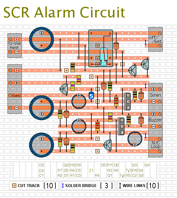
expandable scr based burglar alarm
This is a simple SCR-based burglar alarm circuit. Its features include automatic exit and entry delays, along with a timed bell cut-off and reset. The basic alarm has a single zone, which is adequate for many situations. However, the modular...

4 i n 1 burglar alarm circuit diagram
In this circuit, the alarm is activated under four different conditions: 1. When light falls on LDR1 (located at the entry to the premises). 2. When light falling on LDR2 is obstructed. 3. When door switches are opened or a...

Menci alarm produced schematic circuit diagram
The alarm circuit operates as follows: When the power switch SW1 is turned on, the alarm system becomes active. If a magnet is brought close to the spring, the magnetic field attracts the spring, causing the dynamic and static switch...

Plug-in speed control for tools or appliances
Most standard household appliances and portable hand tools can be adapted for variable-speed operation using a simple half-wave SCR phase control. This device can serve as the speed control unit for typical loads, provided they utilize series universal (brush type)...