


Mains Failure Indicator

Description: When the mains voltage is present at the input terminals, the transistor in the optocoupler is activated, T1 is off, and the silicon-controlled rectifier (SCR) Th1 is in the conducting state. As a result, both terminals of the piezoelectric buzzer are at the same potential, rendering the buzzer inactive. If the mains voltage drops, transistor T1 conducts, connecting one terminal of the buzzer to ground while the thyristor remains conducting. This creates a sufficient potential difference across both the buzzer and diode D5, which indicates the mains failure both audibly and visibly. Upon restoration of mains power, the circuit reverts to its original state. Pressing the reset button interrupts the current through the SCR, placing the thyristor in the blocking state and connecting the other terminal of the buzzer to ground. The unit operates on a 9-V battery, drawing a quiescent current of 1.7-2.5 mA. Proper insulation of the enclosure is essential. If the circuit to the optocoupler and resistor R2 is inadvertently broken, electrolytic capacitor C2 may be damaged due to charging above its 25-V rating. Additionally, when using a plug for mains connection, it is advisable to solder a 1-ohm resistor across capacitor C1 to ensure that it does not retain charge after the plug is removed from the mains socket.
The circuit described operates as a mains failure detection system utilizing an optocoupler for isolation and a piezoelectric buzzer for audible alerts. The optocoupler's transistor serves as a switch that is activated when mains voltage is present, ensuring that the SCR remains off and the buzzer inactive. The SCR, once triggered, maintains its conducting state even when the mains voltage drops, due to its latching behavior. In this scenario, the potential difference created across the buzzer and diode D5 becomes sufficient to activate both components, providing a clear indication of power loss.
The reset mechanism is critical for restoring the circuit to its normal operational state. When the reset button is pressed, the current path through the SCR is interrupted, allowing the thyristor to stop conducting. This action effectively grounds the buzzer, silencing it until the next occurrence of mains failure. The design's reliance on a 9-V battery ensures portability and ease of use, while the low quiescent current minimizes battery drain.
Careful consideration must be given to the enclosure's insulation to prevent accidental short circuits, particularly in the region surrounding the optocoupler and associated components. The risk of damage to capacitor C2 is a significant concern; thus, it is imperative to maintain the integrity of the circuit connections. The recommendation to include a resistor across capacitor C1 serves as a safety measure, discharging the capacitor when the mains supply is disconnected, thereby preventing potential hazards during maintenance or service. Overall, this design effectively combines simplicity and functionality to provide reliable mains failure detection and alerting capabilities. When the mains voltage is present at the input terminals, the transistor in the optocoupler is on, T1 is off, and s ilicon-controlled rectifier Thl is in the conducting state. Because both terminals of the piezoelectric buzzer are then at the same potential, the buzzer is inactive. If the mains voltage drops out, transistor T1 conducts and causes one of the terminals of the buzzer to be connected to earth; the thyristor remains in the conducting state.
In this situation, a large enough potential difference is across both the buzzer and D5 to cause these elements to indicate the mains failure—both audibly and visibly. When the mains is restored, the circuit returns to its original state. A touch on the reset button then interrupts the current through the SCR so that the thyristor goes into the blocking state, and the other terminal of the buzzer is connected to ground.
The unit is powered by a 9-V battery and draws a quiescent current of 1.7-2.5 mA. It is important for the enclosure to be well-insulated. If by accident the circuit to the optocoupler and R2 is broken, electrolytic capacitor C2 might be damaged because it will be charged well above its 25-V rating. Secondly, where a plug is used for the mains connection, it is advisable to solder a 1- resistor across CI so that this capacitor does not retain its charge after the plug is removed from the mains socket.
The circuit described operates as a mains failure detection system utilizing an optocoupler for isolation and a piezoelectric buzzer for audible alerts. The optocoupler's transistor serves as a switch that is activated when mains voltage is present, ensuring that the SCR remains off and the buzzer inactive. The SCR, once triggered, maintains its conducting state even when the mains voltage drops, due to its latching behavior. In this scenario, the potential difference created across the buzzer and diode D5 becomes sufficient to activate both components, providing a clear indication of power loss.
The reset mechanism is critical for restoring the circuit to its normal operational state. When the reset button is pressed, the current path through the SCR is interrupted, allowing the thyristor to stop conducting. This action effectively grounds the buzzer, silencing it until the next occurrence of mains failure. The design's reliance on a 9-V battery ensures portability and ease of use, while the low quiescent current minimizes battery drain.
Careful consideration must be given to the enclosure's insulation to prevent accidental short circuits, particularly in the region surrounding the optocoupler and associated components. The risk of damage to capacitor C2 is a significant concern; thus, it is imperative to maintain the integrity of the circuit connections. The recommendation to include a resistor across capacitor C1 serves as a safety measure, discharging the capacitor when the mains supply is disconnected, thereby preventing potential hazards during maintenance or service. Overall, this design effectively combines simplicity and functionality to provide reliable mains failure detection and alerting capabilities. When the mains voltage is present at the input terminals, the transistor in the optocoupler is on, T1 is off, and s ilicon-controlled rectifier Thl is in the conducting state. Because both terminals of the piezoelectric buzzer are then at the same potential, the buzzer is inactive. If the mains voltage drops out, transistor T1 conducts and causes one of the terminals of the buzzer to be connected to earth; the thyristor remains in the conducting state.
In this situation, a large enough potential difference is across both the buzzer and D5 to cause these elements to indicate the mains failure—both audibly and visibly. When the mains is restored, the circuit returns to its original state. A touch on the reset button then interrupts the current through the SCR so that the thyristor goes into the blocking state, and the other terminal of the buzzer is connected to ground.
The unit is powered by a 9-V battery and draws a quiescent current of 1.7-2.5 mA. It is important for the enclosure to be well-insulated. If by accident the circuit to the optocoupler and R2 is broken, electrolytic capacitor C2 might be damaged because it will be charged well above its 25-V rating. Secondly, where a plug is used for the mains connection, it is advisable to solder a 1- resistor across CI so that this capacitor does not retain its charge after the plug is removed from the mains socket.

Common base transistor amplifier circuit of a unit
A common base transistor amplifier circuit is characterized by its basic structure, which includes key components such as a biasing resistor, capacitors for coupling, and an amplifying transistor. The circuit features four resistors that establish the quiescent point, with the...

transistor amplifier self bias
The simplest way to bias a transistor amplifier is through a fixed-bias circuit. The supply voltage is connected to the base terminal of the transistor via the R1 current-limiting resistor. The bias resistor value is typically chosen based on the...

Mains Remote-Alert circuit
Pressing the pushbutton on the transmitter activates a sound and/or light alert in the receiver. This system operates without wiring or radio frequencies; instead, the transmitted signal is conveyed through the mains supply line. It is suitable for use in...

microcontroller Why this transistor logic as switch is not working
The remote control of an RC car was modified by extending wires from the backward, forward, left, and right switches. Grounding any of these wires completes the circuit and sends a signal to the car. The intention is to close...

Transistor Circuits Design
Transistors are essential components of electronic circuits. The success of a circuit design depends on the selection of the appropriate transistor type and the calculations involved.
Transistors serve as fundamental building blocks in electronic circuits, playing critical roles in amplification, switching,...

Five-transistor amplifier
The circuit operates from DC to 50 MHz and is capable of delivering pulses as short as 10 ns. It is driven by a TTL signal through a 740S00 quad Schottky NAND gate, with input connections made via ICA and...

Transistor attenuation - feedback tone circuit
Figure 4-11 illustrates a feedback attenuator that comprises a transistor-based tone control circuit. This circuit features a conventional high and bass control system, along with balance control, volume control, loudness adjustment, and subwoofer control, as well as field sense control....
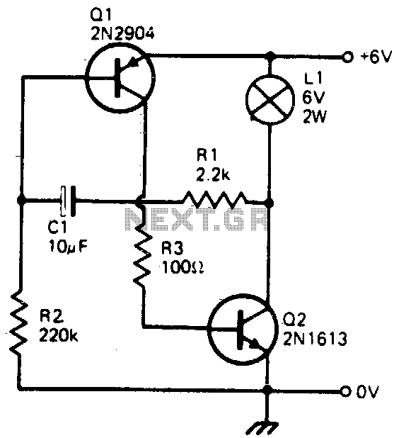
Transistorized flasher
This simple circuit will flash a 6-volt lamp at a rate determined by the size of capacitor C1. It is most economical on power as it only draws current when the lamp is on. When the lamp is off, both...

2 channel audio mixer circuit using transistors
This two-channel audio mixer utilizes 2N3904 transistors to create two preamplifiers. The first preamplifier is designed for high gain, suitable for microphone input, while the second preamplifier allows for control over the audio level input. The audio mixer requires a...