


Natural gas stove flame alarm

Description: After the gas stove ignition, closing switch S, the circuit is operational. The phototransistor VT1, exposed to flame, remains in a low resistance state. This causes transistor VT2 to enter saturated conduction. Transistor VT3 and the integrated circuit (IC) are connected to the collector, which keeps the trigger terminal of the IC at a low potential, preventing it from functioning, and the speaker BL remains silent. If, during the combustion process, the gas stove unexpectedly goes out, VT1 will no longer receive strong light irradiation, leading to an increase in its internal resistance. Consequently, VT2 exits saturation, and the trigger terminal of the IC rises to a high level, activating the IC. This allows the music signal emitted by the crystal tube VT3 to amplify, prompting the speaker BL to issue a birdsong alarm to alert the owner to close the gas valve. The transistors VT1 and VT2 are rated at approximately 500.
The circuit operates as a safety mechanism for gas stoves, utilizing phototransistor VT1 to detect the presence of flame. When the stove is ignited and switch S is closed, the circuit enters a normal operating mode. The phototransistor VT1, under the influence of the flame, maintains a low resistance, which ensures that transistor VT2 is in a saturated state. This condition allows the circuit to keep the IC's trigger terminal at a low voltage, thus preventing any output signal from being generated, and the speaker BL remains inactive.
In the event that the flame goes out unexpectedly, the lack of light causes VT1 to increase its resistance, which in turn leads to the saturation state of VT2 being disrupted. As VT2 exits saturation, the voltage at the IC's trigger terminal rises, allowing the IC to become active. This activation results in the generation of a music signal from the crystal tube VT3, which is then amplified and sent to the speaker BL. The output is designed to produce a birdsong alarm, effectively alerting the user to the dangerous situation of a gas leak, prompting them to take immediate action to close the gas valve.
The circuit incorporates transistors VT1 and VT2, which are specified to handle currents of approximately 500 mA, ensuring that they can manage the necessary power levels without overheating or failing. This design is crucial for the reliability of the safety system, providing a robust response to the loss of flame and ensuring that the user is promptly notified of any potential hazards associated with gas usage.After the gas stove ignition, closing switch S, the circuit is in working condition. Phototransistor VT1 by flame before irradiation, low resistance state, the transistor VT2: saturated conduction, VT3 and integrated sheet music collector connected to the trigger terminal of the IC at a low potential, lC does not work, the speaker BL does not sound. If the gas stove in the combustion process for some reason suddenly went out, VT1 lose strong light irradiation, the internal resistance increases, VT2 exit saturation tends deadline, 1C trigger terminal is at a high level, Ic work, the music signal emitted by the crystal tube VT3 zoom promote BL issued birdsong alarm to alert the owner to close coal gas valve. In addition to the figure stated, transistors VT1 and VT2 of ~ 500.
The circuit operates as a safety mechanism for gas stoves, utilizing phototransistor VT1 to detect the presence of flame. When the stove is ignited and switch S is closed, the circuit enters a normal operating mode. The phototransistor VT1, under the influence of the flame, maintains a low resistance, which ensures that transistor VT2 is in a saturated state. This condition allows the circuit to keep the IC's trigger terminal at a low voltage, thus preventing any output signal from being generated, and the speaker BL remains inactive.
In the event that the flame goes out unexpectedly, the lack of light causes VT1 to increase its resistance, which in turn leads to the saturation state of VT2 being disrupted. As VT2 exits saturation, the voltage at the IC's trigger terminal rises, allowing the IC to become active. This activation results in the generation of a music signal from the crystal tube VT3, which is then amplified and sent to the speaker BL. The output is designed to produce a birdsong alarm, effectively alerting the user to the dangerous situation of a gas leak, prompting them to take immediate action to close the gas valve.
The circuit incorporates transistors VT1 and VT2, which are specified to handle currents of approximately 500 mA, ensuring that they can manage the necessary power levels without overheating or failing. This design is crucial for the reliability of the safety system, providing a robust response to the loss of flame and ensuring that the user is promptly notified of any potential hazards associated with gas usage.After the gas stove ignition, closing switch S, the circuit is in working condition. Phototransistor VT1 by flame before irradiation, low resistance state, the transistor VT2: saturated conduction, VT3 and integrated sheet music collector connected to the trigger terminal of the IC at a low potential, lC does not work, the speaker BL does not sound. If the gas stove in the combustion process for some reason suddenly went out, VT1 lose strong light irradiation, the internal resistance increases, VT2 exit saturation tends deadline, 1C trigger terminal is at a high level, Ic work, the music signal emitted by the crystal tube VT3 zoom promote BL issued birdsong alarm to alert the owner to close coal gas valve. In addition to the figure stated, transistors VT1 and VT2 of ~ 500.

Flash Slave Trigger
Flash slaves are utilized to enhance a primary flash unit by adding one or more supplementary flash units. The slave trigger detects the initial flash through a phototransistor and subsequently activates the additional flashes with a delay of a few...

A three-alarm phase circuits
The circuit features intermediate relays KAi, KA2, and KA3, which are connected to the outlet end of the low-voltage circuit breakers. An alarm circuit is linked to a backup power supply or a battery power supply. This configuration serves to...
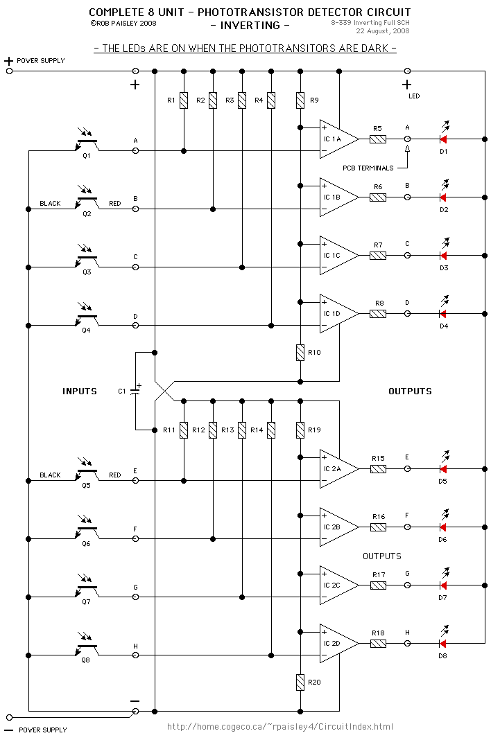
Photo Inverting
For phototransistors, a resistance value of 470K ohms is suitable for most ambient light conditions. In cases of dim lighting, a higher resistor value, such as 1 Megohm, can enhance sensitivity. This high-impedance test voltmeter circuit is also applicable for...

5 Zone Alarm Circuit
Each zone uses a normally closed contact. These can be micro switches or standard alarm contacts (usually reed switches). Zone 1 is a timed zone which must be used as the entry and exit point of the building. Zones 2...

simple optical switch
When the phototransistor is illuminated by infrared (IR) light, it begins to conduct, causing the voltage between a 1 MΩ resistor (chosen arbitrarily) and the phototransistor to decrease from VCC to lower values. When this voltage falls below VCC/3, the...

Simple Amplifier For Phototransistors Circuit
This simple amplifier is compatible with nearly any phototransistor. Although the 741 operational amplifier is designed for use with a split supply, it can also function effectively with a single-sided supply.
The described amplifier circuit utilizes the 741 operational amplifier (op-amp),...

Elderly lost alarm circuit
The circuit utilizes an RMIB multivibrator component that operates at a maximum distance. When the distance exceeds a specific threshold, the output pin of the receiver goes low, effectively stopping the oscillation. The NE555 multivibrator, which is part of the...

Simple optical switchs
When the phototransistor is struck by infrared (IR) light, it begins to conduct, causing the voltage across a 1 MΩ resistor (chosen arbitrarily) and the phototransistor to drop from VCC to lower values. When this voltage falls below VCC/3, the...
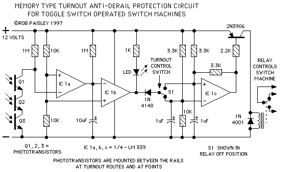
Protector
The circuits presented here will prevent turnouts from being thrown while a train is on a switch, which is ideal in situations where the switch cannot be seen by the operator. They utilize phototransistor sensors to detect the presence of...