


Networking Security System (ATmega16L)
#ATmega16L
#PIR sensor
#Ethernet
#TCP
#home security
#microcontroller
#LCD display
#keypad
#voltage regulator

Description: TCP based security system using the Ethernet module offered within the contest, an ATmega16L microcontroller, a PIR as a sensor and few other peripheral devices, which is specially targeted for homes and small business owners. I have used through for my final design a combination of the WIZ810MJ module, an ATmega16L microcontroller, a 7.3728 MHz crystal (compatible with my bootloader programmer), a DS1302 timekeeper, a PIR to sense the human movement through the body heat, a keypad for initial configuration and a 2×16 LCD for display. The design also include regulators to power up the circuits. More: Well, the system should be installed near an internet source and a cable (crossover or straight-through as it depends) should be plugged in to the module's RJ-45 jack.
If the system is in rest mode (acting as TCP server). It waits for commands from the client (its IP address can be programmed or changed initially or during operation) and execute them (after a password is entered obviously) while still inspecting for any Alarm which would arise from the PIR sensor. When any Alarm triggers, it switches into client mode (acts as a TCP client) and starts sending warning signs.
The system uses motion sensing (based on human body heat) to trigger an alarm which sends a message to the server containing a timestamp presenting the exact time the Motion was detected acting as a real-time surveillance system. For increasing safety from the risk arising from a false alarm, it sends the alarm signals for about 5 minutes and then it stops for 10 minutes and so on assuming the alarm was still active... Clearing the way for the customer to stop the alarm if he noticed some kind of a failure as the system acts as a server in these 10 minutes. This false alarm is very rare and it could occur as a result of maybe a passing squirrel or some relative passed by and forgot to turn the alarm off... etc. So although it is rare but should be taken care of. In the first start-up of the system, it enters the configuration mode. It is just a feature that I added for the design to be more flexible. The System asks you first (through the LCD interface) to enter a 4 digit password, I didn’t do a masking feature because I sense there would be less error when you can really see the password written on the LCD, and there isn’t off course any viruses or key loggers are there?!
The system will also ask you about the current date and time which is necessary for the validity of the timestamp associated with the Alarms. Otherwise, if the time was mis-entered, the customer may lose track of when the alarm was really triggered.
After entering the current date the system asks the customer to choose between accepting the default IP setting or reconfigure them depending on his own needs. The customer will be asked to enter the System IP Address, the subnet mask, the default gateway address, the MAC address desired, and the destination or Server IP address in which will give commands remotely to the security system and will also receive Alarm signals when the motion is sensed. and here ends the configuration, I didn’t really see any more necessary feature to add to the configuration, but this doesn’t block the way for future improvement as minor adjustments could be made and the user could be given more flexibility in the future versions. Once it is connected and powered on, (it takes power from 3 sources, 3.3v, 5v, and 12v for the PIR) the system enters into the configuration mode.
The described TCP-based security system integrates several key components to ensure effective monitoring and control. The ATmega16L microcontroller serves as the central processing unit, managing the interactions between the various peripherals. The WIZ810MJ Ethernet module facilitates network connectivity, allowing the system to communicate with a remote server over TCP/IP.
The PIR sensor is crucial for detecting human movement through infrared sensing, triggering alarms based on changes in body heat. The system's operational modes include a server mode for awaiting commands and a client mode for alerting the server upon detecting movement. The configuration interface is user-friendly, utilizing a 2×16 LCD display and a keypad for input, making the system accessible for initial setup and adjustments.
The power supply design incorporates voltage regulators to accommodate the different voltage requirements of the system components, ensuring stable operation. The DS1302 real-time clock module is essential for maintaining accurate timestamps, which are critical for logging alarm events.
The alarm signaling mechanism is designed to mitigate false alarms by implementing a timed response strategy, where alerts are sent for a duration of five minutes followed by a ten-minute cooldown period. This approach allows users to verify the validity of an alarm without overwhelming them with notifications.
Overall, the system is tailored for ease of use and flexibility, with provisions for future enhancements to expand its functionality. The configuration process allows users to set their security preferences, including IP settings and alarm parameters, ensuring the system can adapt to different environments and user needs.TCP based security system using the Ethernet module offered within the contest , an ATmega16L microcontroller , a PIR as a sensor and few other peripheral devices , which is specially targeted for homes and small business owners. I have used through for my final design a combination of the WIZ810MJ module , an ATmega16L microcontroller , a 7.3728 MHz crystal (compatible with my bootloader programmer), a DS1302 timekeeper , a PIR to sense the human movement through the body heat , a keypad for initial configuration and a 2×16 LCD for display.
The design also include regulators to power up the circuits. Well , the system should be installed near an internet source and a cable (crossover or straight-through as it depends) should be plugged in to the module?s Rj-45 jack. If the system is in rest mode (acting as TCP server) . It waits for commands from the client (its IP address can be programmed or change initially or during operation) and execute them (after a password is entered obviously )while still inspecting for any Alarm which would arises from the PIR sensor .
When any Alarm triggers , it switches into client mode (acts as a TCP client) and starts sending warning signs. The system uses motion sensing (based on human body heat) to trigger an alarm which sends a message to the server containing a timestamp presenting the exact time the Motion was detected acting as a real-time surveillance system .
For increasing safety from the risk arising from a false alarm , it sends the alarm signals for about 5 minutes and then it stops for 10 minutes and so on assuming the alarm was still active ... Clearing the way for the costumer to stop the alarm if he noticed some kind of a failure as the system acts as a server in these 10 minutes.
This false alarm is very rare and it could occur as a result of maybe a passing squirrel maybe or some relative passed by and forgot to turn the alarm off .. etc .. So although it is rare but should be taken care of. In the first start-up of the system, it enters the configuration mode . It is just a feature that I added for the design to be more flexible. The System asks you first (through the LCD interface) to enter a 4 digit password , I didn?t do a masking feature because I sense there would be less error when you can really see the password written on the LCD , and there isn?t off course any viruses or key loggers are there ?!
The system will also ask you about the current date and time which is necessary for the validity of the timestamp associated with the Alarms. Otherwise, if the time was miss-entered ,the customer may lose track of when the alarm was really triggered.
After entering the current date the system asks the customer to chose between accepting the default IP setting or reconfigure them depending on his own needs . The customer will be asked to enter the System IP Address ,the subnet mask, the default gateway address , the MAC address desired , and the destination or Server IP address in which will give commands remotely to the security system and will also receive Alarm signals when the motion is sensed .
and here ends the configuration , I didn?t really see any more necessary feature to add to the configuration ,but this doesn?t block the way for future improvement as minor adjustments could be made and the user could be given more flexibility in the future versions. Once it is connected and powered on , (it takes power from 3 sources ,3.3v ,5v,and 12 v for the PIR) the system enters into the configuration mode .
If the system is in rest mode (acting as TCP server). It waits for commands from the client (its IP address can be programmed or changed initially or during operation) and execute them (after a password is entered obviously) while still inspecting for any Alarm which would arise from the PIR sensor. When any Alarm triggers, it switches into client mode (acts as a TCP client) and starts sending warning signs.
The system uses motion sensing (based on human body heat) to trigger an alarm which sends a message to the server containing a timestamp presenting the exact time the Motion was detected acting as a real-time surveillance system. For increasing safety from the risk arising from a false alarm, it sends the alarm signals for about 5 minutes and then it stops for 10 minutes and so on assuming the alarm was still active... Clearing the way for the customer to stop the alarm if he noticed some kind of a failure as the system acts as a server in these 10 minutes. This false alarm is very rare and it could occur as a result of maybe a passing squirrel or some relative passed by and forgot to turn the alarm off... etc. So although it is rare but should be taken care of. In the first start-up of the system, it enters the configuration mode. It is just a feature that I added for the design to be more flexible. The System asks you first (through the LCD interface) to enter a 4 digit password, I didn’t do a masking feature because I sense there would be less error when you can really see the password written on the LCD, and there isn’t off course any viruses or key loggers are there?!
The system will also ask you about the current date and time which is necessary for the validity of the timestamp associated with the Alarms. Otherwise, if the time was mis-entered, the customer may lose track of when the alarm was really triggered.
After entering the current date the system asks the customer to choose between accepting the default IP setting or reconfigure them depending on his own needs. The customer will be asked to enter the System IP Address, the subnet mask, the default gateway address, the MAC address desired, and the destination or Server IP address in which will give commands remotely to the security system and will also receive Alarm signals when the motion is sensed. and here ends the configuration, I didn’t really see any more necessary feature to add to the configuration, but this doesn’t block the way for future improvement as minor adjustments could be made and the user could be given more flexibility in the future versions. Once it is connected and powered on, (it takes power from 3 sources, 3.3v, 5v, and 12v for the PIR) the system enters into the configuration mode.
The described TCP-based security system integrates several key components to ensure effective monitoring and control. The ATmega16L microcontroller serves as the central processing unit, managing the interactions between the various peripherals. The WIZ810MJ Ethernet module facilitates network connectivity, allowing the system to communicate with a remote server over TCP/IP.
The PIR sensor is crucial for detecting human movement through infrared sensing, triggering alarms based on changes in body heat. The system's operational modes include a server mode for awaiting commands and a client mode for alerting the server upon detecting movement. The configuration interface is user-friendly, utilizing a 2×16 LCD display and a keypad for input, making the system accessible for initial setup and adjustments.
The power supply design incorporates voltage regulators to accommodate the different voltage requirements of the system components, ensuring stable operation. The DS1302 real-time clock module is essential for maintaining accurate timestamps, which are critical for logging alarm events.
The alarm signaling mechanism is designed to mitigate false alarms by implementing a timed response strategy, where alerts are sent for a duration of five minutes followed by a ten-minute cooldown period. This approach allows users to verify the validity of an alarm without overwhelming them with notifications.
Overall, the system is tailored for ease of use and flexibility, with provisions for future enhancements to expand its functionality. The configuration process allows users to set their security preferences, including IP settings and alarm parameters, ensuring the system can adapt to different environments and user needs.TCP based security system using the Ethernet module offered within the contest , an ATmega16L microcontroller , a PIR as a sensor and few other peripheral devices , which is specially targeted for homes and small business owners. I have used through for my final design a combination of the WIZ810MJ module , an ATmega16L microcontroller , a 7.3728 MHz crystal (compatible with my bootloader programmer), a DS1302 timekeeper , a PIR to sense the human movement through the body heat , a keypad for initial configuration and a 2×16 LCD for display.
The design also include regulators to power up the circuits. Well , the system should be installed near an internet source and a cable (crossover or straight-through as it depends) should be plugged in to the module?s Rj-45 jack. If the system is in rest mode (acting as TCP server) . It waits for commands from the client (its IP address can be programmed or change initially or during operation) and execute them (after a password is entered obviously )while still inspecting for any Alarm which would arises from the PIR sensor .
When any Alarm triggers , it switches into client mode (acts as a TCP client) and starts sending warning signs. The system uses motion sensing (based on human body heat) to trigger an alarm which sends a message to the server containing a timestamp presenting the exact time the Motion was detected acting as a real-time surveillance system .
For increasing safety from the risk arising from a false alarm , it sends the alarm signals for about 5 minutes and then it stops for 10 minutes and so on assuming the alarm was still active ... Clearing the way for the costumer to stop the alarm if he noticed some kind of a failure as the system acts as a server in these 10 minutes.
This false alarm is very rare and it could occur as a result of maybe a passing squirrel maybe or some relative passed by and forgot to turn the alarm off .. etc .. So although it is rare but should be taken care of. In the first start-up of the system, it enters the configuration mode . It is just a feature that I added for the design to be more flexible. The System asks you first (through the LCD interface) to enter a 4 digit password , I didn?t do a masking feature because I sense there would be less error when you can really see the password written on the LCD , and there isn?t off course any viruses or key loggers are there ?!
The system will also ask you about the current date and time which is necessary for the validity of the timestamp associated with the Alarms. Otherwise, if the time was miss-entered ,the customer may lose track of when the alarm was really triggered.
After entering the current date the system asks the customer to chose between accepting the default IP setting or reconfigure them depending on his own needs . The customer will be asked to enter the System IP Address ,the subnet mask, the default gateway address , the MAC address desired , and the destination or Server IP address in which will give commands remotely to the security system and will also receive Alarm signals when the motion is sensed .
and here ends the configuration , I didn?t really see any more necessary feature to add to the configuration ,but this doesn?t block the way for future improvement as minor adjustments could be made and the user could be given more flexibility in the future versions. Once it is connected and powered on , (it takes power from 3 sources ,3.3v ,5v,and 12 v for the PIR) the system enters into the configuration mode .

LCD Display with Microcontroller
This document outlines the connection of a 16x2 LCD display to a microcontroller, specifically the PIC 16F877A. The circuit diagram is provided, although power supply and oscillator connections for both the PIC and LCD are not depicted. The LCD typically...

Eight-digit-microprocessor-display
The display interface utilizes the ICM7218A/B in conjunction with an 8048 family microcontroller. An 8-bit data bus (DBO/DB7-IDO/ID7) facilitates the transfer of control and data information to the 7218 display interface during successive WRITE pulses. The mode input pins on...

Electronic Keypad
The alarm will switch off when the 4 keys connected to "A,B,C,D" are pushed in the right order. The circuit works because each gate stands upon its predecessor. If any key other than the correct key is pushed, then gate...

control interfacing keypad and lcd
This circuit is designed for interfacing an I/O keypad and an LCD, allowing students to gain hands-on experience with basic I/O device interfacing using the HCS12 microcontroller mounted on the CML12S-DP256 development board. The keypad utilized in this circuit is...

keypad controlled switch
This is a simplified version of the 4-Digit Keypad Controlled Switch. The design has been modified to reduce circuit complexity and the number of components required. Consequently, the code is somewhat less secure, but it should be sufficient for many...
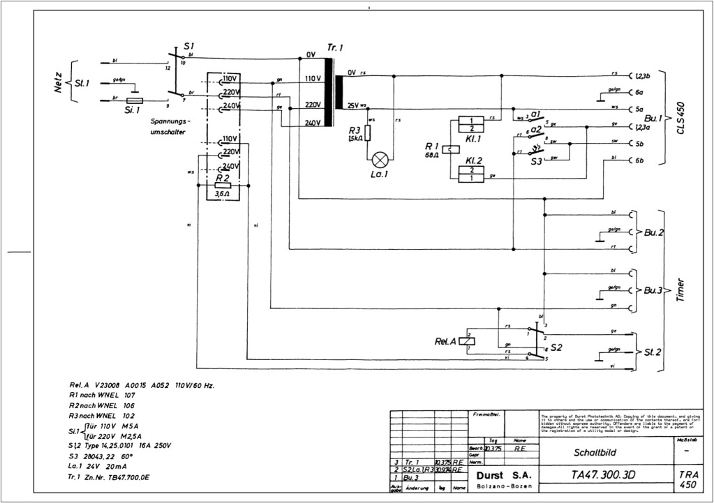
Durst power supplies EST 301 and EST 450
The regulator board of the ES301 has been inspected, revealing that the PCB contacts of the current sensing resistors R42 and R43 are severely burned. There is a nearby group of resistors that also need to be replaced, but their...

Protecting Microcontroller Input Pins from Soft Power Switch
A soft power switch for a microcontroller is designed such that a momentary switch can activate the circuit, including the microcontroller. When the switch is pressed a second time, the microcontroller is capable of shutting itself down after executing necessary...

Robo Atmega328p project
This project was designed to introduce a friend to microcontrollers and circuits using various functionalities and spare parts. A PS2 numpad was utilized as the key entry mechanism, which was found at a thrift store and included the necessary connector....

A 4-Digit Keypad Controlled Switch circuit
This is a universal version of the four-digit alarm control keypad. The design has been modified to free up the relay contacts, allowing the circuit to function as a general-purpose switch. A single pole changeover (SPCO) or single pole double...