


Rain detector electronic circuit project
#rain detector
#transistor
#audio oscillator
#alarm circuit
#sense pad
#simple circuit
#warning system
#liquid detection

Description: This rain detector electronic circuit project is a simple alarm circuit that activates an audio warning when liquid is detected on the sense pad. The circuit diagram is based on two transistors. When the sense pad conducts, transistors Tr1 and Tr2 form an audio oscillatory circuit that generates a pitch sound. This circuit requires a 12-volt power supply, and the speaker should have an impedance of 32 ohms. The sense pad can be constructed on a small piece of printed circuit board.
The rain detector circuit operates by utilizing two transistors configured in a feedback loop to create an oscillator. The sense pad, which is the primary sensing element, is designed to detect the presence of liquid. It can be fabricated using conductive materials on a printed circuit board (PCB) to ensure proper sensitivity and reliability.
Upon contact with liquid, the sense pad completes the circuit, allowing current to flow through Tr1 and Tr2. This leads to the generation of an oscillating signal that drives a connected speaker, producing an audible alarm. The frequency of the oscillation can be adjusted by changing the values of the resistors and capacitors in the circuit, thereby allowing customization of the pitch of the sound emitted.
The power supply for this circuit is specified at 12 volts, which is standard for many electronic applications, ensuring compatibility with various power sources. The choice of a 32-ohm speaker is critical for achieving optimal sound output, as it matches the circuit's output characteristics and ensures efficient energy transfer.
In summary, this rain detector circuit is an effective and straightforward solution for alerting users to the presence of rain or liquid. Its design simplicity, combined with the ability to customize sound output, makes it suitable for various applications, including home automation and weather monitoring systems.This rain detector electronic circuit project is an very simple alarm circuit, that will start an audio warning, if the liquid is present on the sense pad. This rain detector electronic circuit diagram is based on two transistors. When the sense pads conducts, Tr1 and Tr2 from an audio oscillatory circuit that will generate a pitch sound.
Th is circuit needs a 12 volts power supply circuit and the speaker needs to have a 32 ohms. The sense pad can be constructed on a small piece of printed circuit board.
The rain detector circuit operates by utilizing two transistors configured in a feedback loop to create an oscillator. The sense pad, which is the primary sensing element, is designed to detect the presence of liquid. It can be fabricated using conductive materials on a printed circuit board (PCB) to ensure proper sensitivity and reliability.
Upon contact with liquid, the sense pad completes the circuit, allowing current to flow through Tr1 and Tr2. This leads to the generation of an oscillating signal that drives a connected speaker, producing an audible alarm. The frequency of the oscillation can be adjusted by changing the values of the resistors and capacitors in the circuit, thereby allowing customization of the pitch of the sound emitted.
The power supply for this circuit is specified at 12 volts, which is standard for many electronic applications, ensuring compatibility with various power sources. The choice of a 32-ohm speaker is critical for achieving optimal sound output, as it matches the circuit's output characteristics and ensures efficient energy transfer.
In summary, this rain detector circuit is an effective and straightforward solution for alerting users to the presence of rain or liquid. Its design simplicity, combined with the ability to customize sound output, makes it suitable for various applications, including home automation and weather monitoring systems.This rain detector electronic circuit project is an very simple alarm circuit, that will start an audio warning, if the liquid is present on the sense pad. This rain detector electronic circuit diagram is based on two transistors. When the sense pads conducts, Tr1 and Tr2 from an audio oscillatory circuit that will generate a pitch sound.
Th is circuit needs a 12 volts power supply circuit and the speaker needs to have a 32 ohms. The sense pad can be constructed on a small piece of printed circuit board.

The Transistor Amplifier-P2
The three circuits described provide a constant current to the LED (or LEDs) when the supply voltage reaches 15V or higher. The second and third circuits can be activated or deactivated through the input line by turning on the top...
speak memory
Mike Licht confesses to the transistor-related misadventures of his youth. The pocket transistor radio is considered essential to mid-20th century American pop music, but its significance extends beyond music itself; it played a vital role in shaping conversations and thoughts...

Micro Inverter by 2N6121
This micro inverter is a small-sized device that modifies energy from a battery, producing an output voltage of approximately 220V AC at 50Hz. The circuit comprises two transistors that function as a pulse oscillator or square wave generator, driving a...
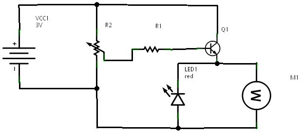
Transistor Current Amplifier Circuit
In a prior post titled "Timing is Everything," the application of PWM (Pulse Width Modulation) signals for controlling devices such as LEDs was discussed. This technique is particularly beneficial when working with digital devices, including microchips and microcontrollers, which often...

SIMPLE DELAY TIMER FOR ONE MINUTE
A simple transistorized one-minute delay timer circuit. It does not include any complex or critical components. This circuit can generate a time delay of approximately one minute. When the switch (preferably a push-button type) is pressed, the LED turns on...

Electronic-bird-chirper
Transistors Q1 and Q2 form the two halves of a free-running multivibrator, with the frequency determined by the voltage across capacitor C8. This capacitor is charged and discharged by the operation of switch S1. Transistors Q3 and Q4 constitute a...
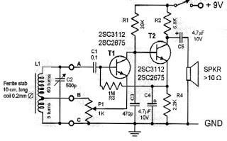
two transistor radio
This circuit is a simple one-transistor Audion type radio powered by a 1.5 V battery. It utilizes a pair of standard low-impedance headphones, wired in series to achieve a total impedance of 64 ohms. The power supply to the circuit...

Transistor Sensor Temperature Measurer
Using the fact that the VRE of a transistor shifts 59.16 mV per decade of current at 25°C. This constant is 0.33%/°C. This V5E-vs.-current relationship holds true regardless of the FBe absolute value. IC, an LT1043, acts as an oscillator...

Rain detector alarm
This circuit gives out an alarm when its sensor is wetted by water. A 555 astable multivibrator is used here which gives a tone of about 1kHz upon detecting water. The sensor when wetted by water completes the circuit and...