


Refrigerator Alarm Circuit
#LDR
#timer
#capacitor
#threshold detection
#square wave generator
#voltage divider
#delay circuit
#sensor

Description: When light strikes the Light Dependent Resistor (LDR), its resistance decreases significantly. The voltage at the junction of the LDR and resistor R2 gradually charges capacitor C2 through resistor R1. After approximately 10 seconds, the voltage across the capacitor reaches the input threshold of operational amplifier U1, which then produces a square wave signal at a frequency of several Hertz. The delay time can be reduced by lowering the value of R1 to 220K ohms. Operational amplifier U2 inverts the signal from U1. This inverted signal activates tone oscillator U3, which remains off when there is no light on the LDR. Finally, operational amplifier U4 amplifies the tone signal produced by U2 and drives a ceramic transducer, resulting in a doubled frequency output at the transducer. The refrigerator alarm circuit operates on a small 9-volt battery, with a current consumption of approximately 0.6 mA in standby mode and 5 mA when the alarm is triggered.
The described circuit functions as a light-sensitive alarm system for refrigerators, utilizing an LDR as the primary sensing element. The LDR decreases its resistance in response to ambient light, allowing the voltage at the junction of the LDR and R2 to rise. This voltage is used to charge capacitor C2 through R1, establishing a time delay before reaching the threshold voltage of operational amplifier U1. The time constant of the charging circuit can be adjusted by changing the resistance value of R1, which directly affects the responsiveness of the system.
Once the threshold is surpassed, U1 outputs a square wave signal that oscillates at a frequency determined by the RC time constant of the charging circuit. U2 serves to invert this signal, providing a complementary output that is necessary for the operation of U3, the tone oscillator. The tone oscillator generates a sound frequency that is typically used for alarm signals, enhancing the alertness of the system.
Importantly, when the LDR is not exposed to light, U3 remains inactive, conserving power. This feature is crucial for battery-operated devices, as it prolongs battery life. U4 amplifies the tone signal to a sufficient level to drive a ceramic transducer, which converts the electrical signal into an audible sound. The doubling of frequency at the transducer provides a more effective alarm sound, making it more noticeable.
The entire circuit is designed to operate efficiently with a standard 9-volt battery, making it suitable for portable applications. The low current consumption in standby mode ensures minimal drain on the battery, while the increased current draw during alarm activation allows for adequate sound output. This design is particularly beneficial for refrigerator applications, where monitoring for light exposure can indicate potential issues with the appliance, such as door openings or malfunctions.When the light falls on the LDR, it becomes low ohmic. The voltage at the junction of LDR/R2 charges the C2 via the R1 slowly. After about 10 seconds, the capacitor voltage reaches the input threshold of U1. Then U1 generates a square wave signal with a frequency of several Hertz. The time delay can be shortened by decreasing the value of R1 down to 220K ©. U2 inverts the signal from U1. This inverted signal switches the U3 tone oscillator. When there is no light hitting the LDR, U3 is turned off. Finally, U4 amplifies the tone signal generated by U2 and drives the ceramic transducer. The frequency is doubled at the transducer. The refrigerator alarm circuit can be powered with a small 9 volts battery. The current consumption is around 0. 6 mA at standby and 5 mA when the alarm is activated.
The described circuit functions as a light-sensitive alarm system for refrigerators, utilizing an LDR as the primary sensing element. The LDR decreases its resistance in response to ambient light, allowing the voltage at the junction of the LDR and R2 to rise. This voltage is used to charge capacitor C2 through R1, establishing a time delay before reaching the threshold voltage of operational amplifier U1. The time constant of the charging circuit can be adjusted by changing the resistance value of R1, which directly affects the responsiveness of the system.
Once the threshold is surpassed, U1 outputs a square wave signal that oscillates at a frequency determined by the RC time constant of the charging circuit. U2 serves to invert this signal, providing a complementary output that is necessary for the operation of U3, the tone oscillator. The tone oscillator generates a sound frequency that is typically used for alarm signals, enhancing the alertness of the system.
Importantly, when the LDR is not exposed to light, U3 remains inactive, conserving power. This feature is crucial for battery-operated devices, as it prolongs battery life. U4 amplifies the tone signal to a sufficient level to drive a ceramic transducer, which converts the electrical signal into an audible sound. The doubling of frequency at the transducer provides a more effective alarm sound, making it more noticeable.
The entire circuit is designed to operate efficiently with a standard 9-volt battery, making it suitable for portable applications. The low current consumption in standby mode ensures minimal drain on the battery, while the increased current draw during alarm activation allows for adequate sound output. This design is particularly beneficial for refrigerator applications, where monitoring for light exposure can indicate potential issues with the appliance, such as door openings or malfunctions.When the light falls on the LDR, it becomes low ohmic. The voltage at the junction of LDR/R2 charges the C2 via the R1 slowly. After about 10 seconds, the capacitor voltage reaches the input threshold of U1. Then U1 generates a square wave signal with a frequency of several Hertz. The time delay can be shortened by decreasing the value of R1 down to 220K ©. U2 inverts the signal from U1. This inverted signal switches the U3 tone oscillator. When there is no light hitting the LDR, U3 is turned off. Finally, U4 amplifies the tone signal generated by U2 and drives the ceramic transducer. The frequency is doubled at the transducer. The refrigerator alarm circuit can be powered with a small 9 volts battery. The current consumption is around 0. 6 mA at standby and 5 mA when the alarm is activated.

wide range timer
A wide range auto turn-off timer covering 1 minute to 20 hours in three ranges.
The auto turn-off timer is designed to provide a versatile timing solution that can be set across a broad spectrum, from a minimum of 1 minute...

Electronic Schematic Diagram of Light Detector Robot using Light Dependent Resistor (LDR)
The electronic schematic of the Light Detector Robot can be divided into three main components: the sensor, the microcontroller, and the DC motor driver. The light sensor utilized in this design is a Light Dependent Resistor (LDR), which alters its...

a tan timer circuit diagram
This timer is designed for individuals seeking to achieve a tan while minimizing excessive exposure to sunlight. A rotary switch adjusts the timer based on six classified photo-types. A photoresistor modifies the preset time according to the brightness of sunlight....

Timer circuit
After one cycle of operation, SCR1 will be activated, resulting in a low voltage being applied to the UJT emitter circuit, which interrupts the tuning function. When pushbutton SI is pressed, or a positive pulse is applied at point A,...
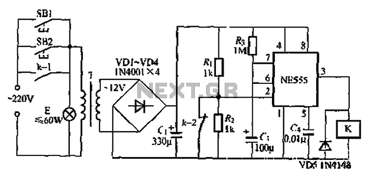
When using the lamp base circuit delay circuit 2
Another application involves the use of a NE555 delay lamp circuit, where components SB1 and SH2 act as J-light buttons that can be installed in two different locations. The lamp can be activated by pressing either SB1 or SB2, which...

The second phase alarm circuit
A capacitor C1 and resistors R1-R3 form a negative sequence voltage filtration device. The resistors and capacitors must meet the following requirements: R1, R2, R3 = 5.5/C1 (KN). The relationship between the resistance and capacitance values is arbitrary. Capacitor selection...

The Time Delay Circuit
The duration for which the circuit remains active is determined by the time required for the stored electrical current to leak back into the circuit, which keeps the transistor and the entire circuit energized. A resistor is present that limits...

Bedside Lamp Timer
The purpose of this circuit is to power a lamp or other apparatus for a specified duration (30 minutes in this case) and then turn it off. It is particularly useful for reading in bed at night, as it automatically...
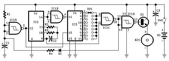
jogging timer circuit diagram
This circuit was developed in response to requests from website visitors for a timer that can emit a beep after intervals of one, two, three minutes, and so forth, for jogging purposes. As depicted in the circuit diagram, SW1 is...