


Room Noise Detector Circuit
#noise detection
#LED indicator
#electret microphone
#op-amp
#sound threshold
#sensitivity control
#low power
#room monitoring
#audio sensor
#signal alert

Description: This circuit is designed to indicate, via a flashing LED, when room noise exceeds a predetermined threshold. The thresholds are set at three fixed levels: 50 dB, 70 dB, and 85 dB. Two operational amplifiers (op-amps) are utilized to amplify the signals captured by a miniature electret microphone, which in turn drives the LED. The circuit is powered by a switch (SW1) that has four positions: the first position turns the circuit off, while the second, third, and fourth positions activate the circuit and adjust the input sensitivity threshold to 85 dB, 70 dB, and 50 dB, respectively. The current consumption is 1 mA when the LED is off and increases to 12-15 mA when the LED is continuously illuminated.
The circuit comprises a miniature electret microphone that serves as the sound input device. The microphone converts sound waves into an electrical signal, which is then fed into the first op-amp configured as a non-inverting amplifier. This stage amplifies the weak audio signal to a suitable level for further processing. The gain of the op-amp can be adjusted depending on the desired sensitivity of the microphone.
Following the first op-amp, the signal is routed to a second op-amp, which further amplifies the signal and may also include a comparator function to determine if the amplified signal exceeds any of the predetermined thresholds. The output of the second op-amp is connected to a threshold detection circuit that utilizes resistors to set the reference voltages corresponding to the 50 dB, 70 dB, and 85 dB levels.
The circuit's operation is controlled by a switch (SW1), which allows the user to select the desired threshold level. In the first position, the circuit is powered off to conserve energy. In the second, third, and fourth positions, the circuit is powered on, and the sensitivity threshold is adjusted accordingly. When the noise level exceeds the selected threshold, the output of the second op-amp triggers a transistor or a similar switching device to activate the LED.
The LED serves as a visual indicator, flashing to signal that the ambient noise level has crossed the set threshold. The flashing behavior can be implemented using a simple timing circuit, which may consist of additional passive components such as resistors and capacitors to create a blinking effect. The current draw of the circuit is relatively low, at 1 mA when the LED is off, and increases to 12-15 mA when the LED is continuously lit, ensuring that the circuit remains efficient while providing clear visual feedback.This circuit is intended to signal, through a flashing LED, the exceeding of a fixed threshold in room noise, chosen from three fixed levels, namely 50, 70 & 85 dB. Two Op-amps provide the necessary circuit gain for sounds picked-up by a miniature electret microphone to drive a LED.
With SW1 in the first position the circuit is off. Second, third and fourth positions power the circuit and set the input sensitivity threshold to 85, 70 & 50 dB respectively. Current drawing is 1mA with LED off and 12-15mA when the LED is steady on..
The circuit comprises a miniature electret microphone that serves as the sound input device. The microphone converts sound waves into an electrical signal, which is then fed into the first op-amp configured as a non-inverting amplifier. This stage amplifies the weak audio signal to a suitable level for further processing. The gain of the op-amp can be adjusted depending on the desired sensitivity of the microphone.
Following the first op-amp, the signal is routed to a second op-amp, which further amplifies the signal and may also include a comparator function to determine if the amplified signal exceeds any of the predetermined thresholds. The output of the second op-amp is connected to a threshold detection circuit that utilizes resistors to set the reference voltages corresponding to the 50 dB, 70 dB, and 85 dB levels.
The circuit's operation is controlled by a switch (SW1), which allows the user to select the desired threshold level. In the first position, the circuit is powered off to conserve energy. In the second, third, and fourth positions, the circuit is powered on, and the sensitivity threshold is adjusted accordingly. When the noise level exceeds the selected threshold, the output of the second op-amp triggers a transistor or a similar switching device to activate the LED.
The LED serves as a visual indicator, flashing to signal that the ambient noise level has crossed the set threshold. The flashing behavior can be implemented using a simple timing circuit, which may consist of additional passive components such as resistors and capacitors to create a blinking effect. The current draw of the circuit is relatively low, at 1 mA when the LED is off, and increases to 12-15 mA when the LED is continuously lit, ensuring that the circuit remains efficient while providing clear visual feedback.This circuit is intended to signal, through a flashing LED, the exceeding of a fixed threshold in room noise, chosen from three fixed levels, namely 50, 70 & 85 dB. Two Op-amps provide the necessary circuit gain for sounds picked-up by a miniature electret microphone to drive a LED.
With SW1 in the first position the circuit is off. Second, third and fourth positions power the circuit and set the input sensitivity threshold to 85, 70 & 50 dB respectively. Current drawing is 1mA with LED off and 12-15mA when the LED is steady on..

Capacitor in parallel with resistor on xoscope amplifier schematic
For capacitor C3, a 100pF capacitor is placed across resistor R2. The circuit functions similarly to previous configurations, although no explanation is provided. The purpose of this component may be self-evident to experienced users, but it may not be clear...

Norton-amplifier
The non-inverting amplifier has a gain of R2/R3 (1 in this case) and produces a voltage of V during a positive excursion of Vin with respect to ground. The inverting amplifier accommodates the negative excursions of V; its gain is...
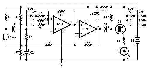
Room Noise Detector Schematic Circuit
This circuit is designed to signal the exceeding of a fixed threshold in room noise through a flashing LED. Three fixed levels are selectable: 50, 70, and 85 dB. Two operational amplifiers provide the necessary gain for sounds captured by...

Continuity Checker
U1 is an operational amplifier used as a comparator. When the test probes are shorted together, resistors R1 and R2 bias the non-inverting input to half the supply voltage. The inverting input is biased by a voltage divider that consists...
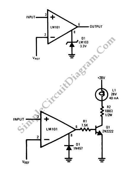
Op-Amp Application: Voltage Comparators
Two reasons why the LM101 is well-suited for comparator applications are its large differential input voltage range and the ease of clamping the output.
The LM101 operational amplifier is particularly advantageous for use in comparator circuits due to its significant differential...

Programmable Inverter/Rectifier
The operational amplifier (op amp) can function as either an inverter or a buffer, depending on the polarity controlled by a switch. When configured as a buffer, the gain remains constant at 1. In contrast, when functioning as an inverter,...

Anatek Lab Supply
The unit is designed around a standard operational amplifier and utilizes easily obtainable components. The reverse-engineered circuit diagram of the Anatek 50-1S variable power supply is shown below. The layout of the circuit board does not appear to be particularly...
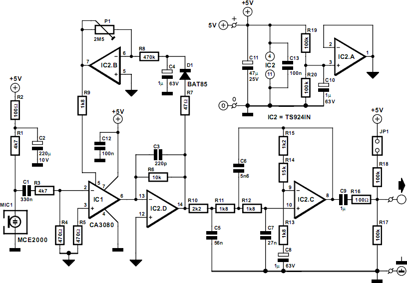
Compressor For Electret Microphone
The FM Remote Control Receiver, found in the Infra-red circuits section of this website, features a connector that provides an analogue output. To create a simple intercom or public address (P.A.) system, a microphone pre-amplifier is required to ensure the...

Single Capacitor Powers Audio Mixer
Micropower and low-voltage operational amplifiers enable the construction of high-performance analog signal processors that do not require batteries or wall transformers. Instead, a capacitor can serve as the power source. The circuit illustrated in Figure 1 depicts an analog mixer...