


Smartcard controlled Lock with Relay
#smartcard
#relay
#access control
#Nutchip
#security
#programmable
#authentication
#locking mechanism
#electronic lock

Description: This design uses a smart card to enable a relay. A Nutchip recognizes its mating smart card among thousand similar ones, because you choose the code to be programmed in the card's memory. No specialized knowledge is necessary, as we supply the card program and codes. Nutchip truth table is simple as well, so you should be able to adapt it to your needs (e.g., adding more than one card, or timing the relay). Even in its actual form, the board is ready to work in many useful applications: open gates e.g. for park lots, access control to gyms, swimming pools, tennis play fields, switch on central heating or showers, or the football field lights, enable TV viewing, photocopying, faxing, coffee machine use, telephones etc. Smartcards are very handy as they are compact, lightweight, and require no batteries. Cards are tough compared to remote controls, are resistant to dirt and wet, and don't break apart falling from a tabletop. If a card gets lost or stolen, you can reprogram the Nutchip in minutes, discarding the old code in favour of a new one, therefore making the old card useless. This card-activated relay requires just a handful of parts and is very simple. The active components in addition to the Nutchip are a 74HC00, a reset generator (IC3) and a transistor for relay switching.
The reset integrated circuit IC3, an MC34064 from Motorola, guarantees a clean Nutchip RESET even in presence of electric noise coming from the power network. Its duty consists of discharging the capacitor C2 as fast as possible when a power drop is detected. But let's introduce the smartcard. We choose a "Funcard Purple": this is the usual name for a card embedding a powerful processor, an Atmel AT90S8515, and a serial EEPROM memory. Other "Funcards" similar to the "Purple" are the "Funcard Prussian" and "Funcard Prussian 256": these should be theoretically compatible, although more expensive. However, please note that we have not tried them, so take our word at your own risk.
As the Funcard Purple embeds a microcontroller, it must be loaded with a program written for this specific task before using it in the circuit. The program is a free download from the file "card_1234.hex", and it is supplied ready-made so only a programmer is needed to get up and running. Once programmed, the Funcard's microcontroller will act as a remote control, generating a pulse train indistinguishable from a radio (RF) remote control. The resulting waveform is output on the smartcard pad labelled "OUT," which connects—through a suitable slot connector—to the Nutchip remote control input (REMOTE, pin 6). A series resistor, R4, is placed to protect the Nutchip from noise and spike pulses that can be generated during card insertion and extraction.
The Nutchip (IC1) is the heart of the device. Nutchip output OUT1 drives an LED (LD1) which is in series with a current-limiting resistor (R3). A separate output is used for driving the relay (RELAY1) through a transistorized relay driver stage (TR1, R2, D1). The transistor functions as an electronic switch, amplifying the Nutchip output current from tenths of mA to tens of mA—a level suitable for driving the relay coil. Diode D1 protects the circuits from high voltages that are induced on the coil during switch-off. A quick prototype can be assembled on a breadboard. Despite the small component count, careful attention is required.
Connections should be kept short, ideally less than 10 cm each. A smartcard connector with clearly visible connections is recommended to prevent errors. Colour-coded wiring is encouraged: red for +5V, black for GND, light blue for 4 MHz buffered clock, green for unbuffered clock, and orange for OUT. Care should be taken not to reverse any part: LED, ICs, and the power supply. In case of doubt, the parts pinout should be checked for details.
Before applying power to the circuit, all connections must be verified against the schematic diagram. Once confirmed, the interface can be connected, power switched on, and the Nutchip programmed. Nutstation software should be used to load the truth table "card.nut," selecting the "custom RF" remote control. Key 1 should be clicked, and "1234" input as the key code. This applies if the default .hex file for the smartcard is used; otherwise, the code should be changed accordingly. The Nutchip must then be programmed.This design uses a smart card to enable a relay. A Nutchip recognizes its mating smart card among thousand similar ones, because you choose the code to be programmed in the card's memory. No speacilized knowledge is necessary, as we supply the card program and codes. Nutchip truth table is simple as well, so you should be able to adapt it to your needs (e.g., adding more than one card, or timing the relay).
Even in its actual form, the board is ready to work in many useful applications: open gates e.g. for park lots. access control to gyms, swimming pools, tennis play fields. switch on central heating or showers, or the football field lights. enable TV viewing, photocopyng, faxing, coffe machine use, telephones etc. Smartcards are very handy as they are compact, lightweight, and require no batteries. Cards are tough compared to remote controls, are resistant to dirt and wet, and don't break apart falling from a tabletop. If a card gets lost or stolen, you can reprogram the Nutchip in minutes, discarding the old code in favour of a new one, therefore making the old card useless.
This card-activated realy requires just an handful of parts and is very simple. The active components in addition to the Nutchip are a 74HC00, a reset generator (IC3) and a transistor for relay switching. Thereset integrated circuit IC3, an MC34064 from Motorola, guarantees a clean Nutchip RESET even in presence of electric noise coming from the power network.
Its duty consists of discharging the capacitor C2 as fast as possible when a power drop is detected. But let's introduce the smartcard. We choose a "Funcard Purple": this is the usual name for a card embedding a powerful processor, an Atmel AT90S8515, and a serial EEPROM memory. Other "Funcards" similar to the "Purple" are the "Funcard Prussian" and "Funcard Prussian 256": these should be theoretically compatible, although more expensive.
However, please note that we have not tried them, so take our word at your own risk. As the Funcard Purple embeds a microcontroller, you must load it with a program written for this specific task before using it in our circuit. The program is a free download from the file "card_1234.hex", and we supply it ready made so you need only a programmer to get up and running.
Once programmed, the Funcard's microcontroller will act as a remote control, generating a pulse train undistinguishible from a radio (RF) remote control. The resulting waveform is output on the smartcard pad labelled "OUT, which connects -though a suitable slot connector- to the Nutchip remote control input (REMOTE, pin 6).
We placed a series resistor, R4, in order to protect the Nutchip from noise and spike pulses that can be generated during card insertion and extraction. The Nutchip (IC1) is the heart of the device. Nutchip output OUT1 drives an LED (LD1) which is in series to a current-limiting resistor (R3). A separate output is used for dirving the relay (RELAY1) through a transistorized relay driver stage (TR1, R2, D1).
The transistor works as an electronic switch, amplifying Nutchip output current from tenths of mA to tens of mA - a level suitable for driving the relay coil. Diode D1 protects the circuits from high voltages that are induced on the coil during switchoff. We assembled a quick prototype on a breadboard. Despite the small component count, a great deal of care and attention is required. The photo show a simplified version of the circuit, which does not include the relay, the associated transistor driver, the RESET circuitry.
This is perfectly OK in order to perform many lab experiments before going for a more definitive implementation, like preparing a printed circuit boards and soldering parts (note: PCB drawings not available). Try to keep connections short, always less that 10 cm each, as shown by the photo. If possible, use a smartcard connector with all of the connection are clearly visible, like ours: this will help preventing errors.
Always use colour-coded wiring: our example uses red for +%V, black for GND, light blue for 4 MHz buffered clock, green for unbuffered clock, orange for OUT. Take care not to revert any part: LED, ICs (the photo shows both with pin 1 towards left side), power supply.
In case of doubt, check the parts pinout page for details. When you are finished with the circuit, and before applying power to the circuit, check once more all the connections. If everything corresponds to the schematic diagram, it is time for connecting the interface, switching on power, and programming the Nutchip.
Run Nutstation and load the truth table "card.nut", and select the "custom RF" remote control. From the remote control selection window click on key 1 and input "1234" as the key code. This applies if you are using the default .hex file for the smartcard, otherwise change it accordingly to the new code.Program the Nutchip.
The reset integrated circuit IC3, an MC34064 from Motorola, guarantees a clean Nutchip RESET even in presence of electric noise coming from the power network. Its duty consists of discharging the capacitor C2 as fast as possible when a power drop is detected. But let's introduce the smartcard. We choose a "Funcard Purple": this is the usual name for a card embedding a powerful processor, an Atmel AT90S8515, and a serial EEPROM memory. Other "Funcards" similar to the "Purple" are the "Funcard Prussian" and "Funcard Prussian 256": these should be theoretically compatible, although more expensive. However, please note that we have not tried them, so take our word at your own risk.
As the Funcard Purple embeds a microcontroller, it must be loaded with a program written for this specific task before using it in the circuit. The program is a free download from the file "card_1234.hex", and it is supplied ready-made so only a programmer is needed to get up and running. Once programmed, the Funcard's microcontroller will act as a remote control, generating a pulse train indistinguishable from a radio (RF) remote control. The resulting waveform is output on the smartcard pad labelled "OUT," which connects—through a suitable slot connector—to the Nutchip remote control input (REMOTE, pin 6). A series resistor, R4, is placed to protect the Nutchip from noise and spike pulses that can be generated during card insertion and extraction.
The Nutchip (IC1) is the heart of the device. Nutchip output OUT1 drives an LED (LD1) which is in series with a current-limiting resistor (R3). A separate output is used for driving the relay (RELAY1) through a transistorized relay driver stage (TR1, R2, D1). The transistor functions as an electronic switch, amplifying the Nutchip output current from tenths of mA to tens of mA—a level suitable for driving the relay coil. Diode D1 protects the circuits from high voltages that are induced on the coil during switch-off. A quick prototype can be assembled on a breadboard. Despite the small component count, careful attention is required.
Connections should be kept short, ideally less than 10 cm each. A smartcard connector with clearly visible connections is recommended to prevent errors. Colour-coded wiring is encouraged: red for +5V, black for GND, light blue for 4 MHz buffered clock, green for unbuffered clock, and orange for OUT. Care should be taken not to reverse any part: LED, ICs, and the power supply. In case of doubt, the parts pinout should be checked for details.
Before applying power to the circuit, all connections must be verified against the schematic diagram. Once confirmed, the interface can be connected, power switched on, and the Nutchip programmed. Nutstation software should be used to load the truth table "card.nut," selecting the "custom RF" remote control. Key 1 should be clicked, and "1234" input as the key code. This applies if the default .hex file for the smartcard is used; otherwise, the code should be changed accordingly. The Nutchip must then be programmed.This design uses a smart card to enable a relay. A Nutchip recognizes its mating smart card among thousand similar ones, because you choose the code to be programmed in the card's memory. No speacilized knowledge is necessary, as we supply the card program and codes. Nutchip truth table is simple as well, so you should be able to adapt it to your needs (e.g., adding more than one card, or timing the relay).
Even in its actual form, the board is ready to work in many useful applications: open gates e.g. for park lots. access control to gyms, swimming pools, tennis play fields. switch on central heating or showers, or the football field lights. enable TV viewing, photocopyng, faxing, coffe machine use, telephones etc. Smartcards are very handy as they are compact, lightweight, and require no batteries. Cards are tough compared to remote controls, are resistant to dirt and wet, and don't break apart falling from a tabletop. If a card gets lost or stolen, you can reprogram the Nutchip in minutes, discarding the old code in favour of a new one, therefore making the old card useless.
This card-activated realy requires just an handful of parts and is very simple. The active components in addition to the Nutchip are a 74HC00, a reset generator (IC3) and a transistor for relay switching. Thereset integrated circuit IC3, an MC34064 from Motorola, guarantees a clean Nutchip RESET even in presence of electric noise coming from the power network.
Its duty consists of discharging the capacitor C2 as fast as possible when a power drop is detected. But let's introduce the smartcard. We choose a "Funcard Purple": this is the usual name for a card embedding a powerful processor, an Atmel AT90S8515, and a serial EEPROM memory. Other "Funcards" similar to the "Purple" are the "Funcard Prussian" and "Funcard Prussian 256": these should be theoretically compatible, although more expensive.
However, please note that we have not tried them, so take our word at your own risk. As the Funcard Purple embeds a microcontroller, you must load it with a program written for this specific task before using it in our circuit. The program is a free download from the file "card_1234.hex", and we supply it ready made so you need only a programmer to get up and running.
Once programmed, the Funcard's microcontroller will act as a remote control, generating a pulse train undistinguishible from a radio (RF) remote control. The resulting waveform is output on the smartcard pad labelled "OUT, which connects -though a suitable slot connector- to the Nutchip remote control input (REMOTE, pin 6).
We placed a series resistor, R4, in order to protect the Nutchip from noise and spike pulses that can be generated during card insertion and extraction. The Nutchip (IC1) is the heart of the device. Nutchip output OUT1 drives an LED (LD1) which is in series to a current-limiting resistor (R3). A separate output is used for dirving the relay (RELAY1) through a transistorized relay driver stage (TR1, R2, D1).
The transistor works as an electronic switch, amplifying Nutchip output current from tenths of mA to tens of mA - a level suitable for driving the relay coil. Diode D1 protects the circuits from high voltages that are induced on the coil during switchoff. We assembled a quick prototype on a breadboard. Despite the small component count, a great deal of care and attention is required. The photo show a simplified version of the circuit, which does not include the relay, the associated transistor driver, the RESET circuitry.
This is perfectly OK in order to perform many lab experiments before going for a more definitive implementation, like preparing a printed circuit boards and soldering parts (note: PCB drawings not available). Try to keep connections short, always less that 10 cm each, as shown by the photo. If possible, use a smartcard connector with all of the connection are clearly visible, like ours: this will help preventing errors.
Always use colour-coded wiring: our example uses red for +%V, black for GND, light blue for 4 MHz buffered clock, green for unbuffered clock, orange for OUT. Take care not to revert any part: LED, ICs (the photo shows both with pin 1 towards left side), power supply.
In case of doubt, check the parts pinout page for details. When you are finished with the circuit, and before applying power to the circuit, check once more all the connections. If everything corresponds to the schematic diagram, it is time for connecting the interface, switching on power, and programming the Nutchip.
Run Nutstation and load the truth table "card.nut", and select the "custom RF" remote control. From the remote control selection window click on key 1 and input "1234" as the key code. This applies if you are using the default .hex file for the smartcard, otherwise change it accordingly to the new code.Program the Nutchip.

Programmable Zener
The ICL8212 is configured as a programmable zener diode, allowing for the programming of zener voltages ranging from 2 V to 30 V by appropriately selecting R2. The zener voltage is influenced by this selection. Additionally, due to the lack...

DC relay circuit to accelerate the release
A DC relay or contactor is utilized to enhance the excitation pull-in and release mechanisms in a circuit. The relay circuit, as depicted in Figure 6-28, facilitates improved return line efficiency. When the control relay KAi is activated, its normally...

Single Transistor Relay Toggle Circuit
The circuit requires a double pole, double throw relay in conjunction with a single transistor to allow toggling the relay with a momentary push button. One set of relay contacts is used to control the load, while the other is...

Electronic Lockers
This circuit is an electronic locker that operates using a combination of switches, functioning based on a specific code. The switch matrix is located on the locker door and consists of 16 switches arranged in a 4x4 grid, totaling eight...

water pump relay controller circuit schematic
This circuit utilizes a relay to control a water pump, enabling automatic level control for a water reservoir or well. The shorter steel rod acts as the "water high" sensor, while the longer rod serves as the "water low" sensor....

Relay Circuit Detects Light Change
Configured with capacitive coupling by inserting a small capacitor between the phototransistor and the bipolar transistor, this relay circuit will respond only to rapid changes.
This relay circuit utilizes capacitive coupling to enhance its responsiveness to fast signal changes. The configuration...

Alternating Relay Switch
A reader named Andrea ([email protected]) submitted a circuit designed for educational purposes. The primary objective is to demonstrate how to electronically toggle an output state using only a push-button switch. According to Andrea, this simple circuit can drive a monostable...
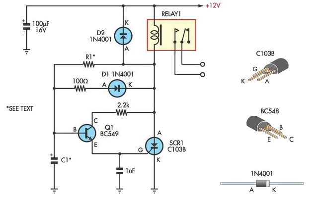
Handy Time Delay With Relay Output
This circuit is designed to provide delayed relay switching action at power on. The delay is a function of the time constant produced by the combination of components.
The circuit operates by utilizing a timing element, typically a resistor-capacitor (RC) network,...

Input switching circuit
A relay is controlled by a closed circuit in a digital logic setup, utilizing a touch input switching circuit.
The described circuit involves a relay that operates based on a closed circuit condition within a digital logic framework. The relay serves...