


Sound Controlled Switch
#sound controlled
#condenser microphone
#op-amp
#LM324
#level detector
#remote switching
#burglar alarm
#two-stage amplifier

Description: Described here is a very inexpensive solution to many phono-controlled applications like remote switching on, for instance, or activating a camera, tape recorder, burglar alarms, toys, etc. The circuit given here employs a condenser microphone as the pick-up. A two-stage amplifier built around a quad op-amp IC LM324 offers a good gain to enable sound pick-up up to four meters. The third op-amp is configured as a level detector whose non-inverting terminal is fed with the amplified and filtered signal available at the output of the second op-amp. The inverting input of the third op-amp is given a reference voltage from a potential divider consisting of a 10k resistor and a 4.7k preset. The 100-ohm resistance in series with the potential divider ensures against the mis-triggering of the circuit by noise. Thus by adjusting the preset one can control the sensitivity (threshold) of the circuit. The sensitivity control thus helps in rejecting any external unwanted sounds which may be picked up by the amplifier. The output of the level detector are square pulses which are used to trigger a flip-flop. The 100mF capacitor connected across the supply also helps in bypassing noise. A well-regulated supply is recommended for proper functioning of the circuit because an unregulated supply can cause noise pulses to appear in the supply rails when the circuit changes over state (especially when a load is connected to the circuit). These pulses can be picked up by the sensitive amplifier which will cause the circuit to again switch over states, resulting in motor-boating noise. Since the circuit operates at 4.5V, it can be easily incorporated in digital circuits. Fig. (b) shows how the circuit can be employed to control the direction of a DC motor. The circuit employs four npn transistors. Transistors T1 and T4 have their bases tied together and they switch on simultaneously when Q output is logic 1. Similarly T2 and T3 conduct when Q output is logic 1. Thus current through the motor changes direction when the flip-flop toggles. Filters connected in the circuit and tuned to different bands of audio frequencies will enable the same circuit to control more than one device. For instance, a high-frequency sound (such as a whistle) can switch on device 1 and a low-frequency sound (such as clapping) can control device 2.
The described circuit represents a versatile and economical solution for various phono-controlled applications, utilizing a condenser microphone for sound detection. The core component, a quad op-amp IC LM324, is configured to create a two-stage amplifier that significantly amplifies audio signals, allowing sound detection from a distance of up to four meters. The output from the second op-amp feeds into a third op-amp, which functions as a level detector. This configuration is crucial as it ensures that only signals above a certain threshold trigger the subsequent actions, thereby filtering out unwanted noise.
The sensitivity of the level detector is adjustable through a potential divider made up of a 10k resistor and a 4.7k preset resistor. A 100-ohm resistor in series with the potential divider provides additional stability against noise-induced triggering, allowing for precise control over the circuit's responsiveness to sound. The output from the level detector generates square pulses that are used to trigger a flip-flop, facilitating the control of other devices in response to sound events.
To ensure reliable operation, particularly in environments with fluctuating power sources, a well-regulated power supply is essential. An unregulated supply may introduce noise into the system, particularly during state changes, potentially causing undesired oscillations or "motor-boating" effects in the audio amplification stage.
The circuit is designed to operate at 4.5V, making it compatible with digital logic circuits. Additionally, it can control the direction of a DC motor through the use of four NPN transistors. The configuration of these transistors allows for the simultaneous activation of specific pairs based on the output state of the flip-flop, thus enabling bidirectional control of the motor.
Moreover, the inclusion of filters tuned to various audio frequency bands enhances the circuit's functionality, allowing it to differentiate between sounds. For example, a high-frequency sound like a whistle can activate one device, while a low-frequency sound such as clapping can activate another, showcasing the circuit's potential for multi-device control based on sound frequency differentiation. This adaptability makes the circuit suitable for a wide range of applications, from simple toy activation to more complex security systems.Described here is a very inexpensive solution to many phono-controlled applications like remote switching on, for instance, or activating a camera, tape recorder, burglar alarms, toys, etc. The circuit given here employs a condenser microphone as the pick-up. A two-stage amplifier built around a quad op-amp IC LM324 offers a good gain to enable sound pick-up upto four metres.
The third op-amp is configured as a level detector whose non-inverting terminal is fed with the amplified and filtered signal available at the output of the second op-amp. The inverting input of the third op-amp is given a reference voltage from a potential divider consisting of a 10k resistor and a 4.7k preset.
The 100-ohm resistance in series with the potential divider ensures against the mis-triggering of the circuit by noise. Thus by adjusting the preset one can control the sensitivity (threshold) of the circuit. The sensitivity control thus helps in rejecting any external unwanted sounds which may be picked up by the amplifier. The output of the level detector are square pulses which are used to trigger a flip-flop. The 100mF capacitor connected across the supply also helps in bypassing noise. A well regulated supply is recommended for proper functioning of the circuit because an unregulated supply can cause noise pulses to appear in the supply rails when the circuit changes-over state (especially when a load is connected to the circuit).
These pulses can be picked up by the sensitive amplifier which will cause the circuit to again switch-over states, resulting into motor-boating noise. Since the circuit operates at 4.5V, it can be easily incorporated in digital circuits. Fig. (b) shows how the circuit can be employed to control the direction of a DC motor. The circuit employs four npn transistors. Transistors T1 and T4 have their bases tied together and they switch-on simultaneously when Q output is logic 1.
Similarly T2 and T3 conduct when Q output is logic 1. Thus current through the motor changes direction when the flip-flop toggles. Filters connected in the circuit and tuned to different bands of audio frequencies will enable the same circuit to control more than one device. For instance, a high frequency sound (such as whistle) can switch on device 1 and a low frequency sound (such as clapping) can control device 2.
The described circuit represents a versatile and economical solution for various phono-controlled applications, utilizing a condenser microphone for sound detection. The core component, a quad op-amp IC LM324, is configured to create a two-stage amplifier that significantly amplifies audio signals, allowing sound detection from a distance of up to four meters. The output from the second op-amp feeds into a third op-amp, which functions as a level detector. This configuration is crucial as it ensures that only signals above a certain threshold trigger the subsequent actions, thereby filtering out unwanted noise.
The sensitivity of the level detector is adjustable through a potential divider made up of a 10k resistor and a 4.7k preset resistor. A 100-ohm resistor in series with the potential divider provides additional stability against noise-induced triggering, allowing for precise control over the circuit's responsiveness to sound. The output from the level detector generates square pulses that are used to trigger a flip-flop, facilitating the control of other devices in response to sound events.
To ensure reliable operation, particularly in environments with fluctuating power sources, a well-regulated power supply is essential. An unregulated supply may introduce noise into the system, particularly during state changes, potentially causing undesired oscillations or "motor-boating" effects in the audio amplification stage.
The circuit is designed to operate at 4.5V, making it compatible with digital logic circuits. Additionally, it can control the direction of a DC motor through the use of four NPN transistors. The configuration of these transistors allows for the simultaneous activation of specific pairs based on the output state of the flip-flop, thus enabling bidirectional control of the motor.
Moreover, the inclusion of filters tuned to various audio frequency bands enhances the circuit's functionality, allowing it to differentiate between sounds. For example, a high-frequency sound like a whistle can activate one device, while a low-frequency sound such as clapping can activate another, showcasing the circuit's potential for multi-device control based on sound frequency differentiation. This adaptability makes the circuit suitable for a wide range of applications, from simple toy activation to more complex security systems.Described here is a very inexpensive solution to many phono-controlled applications like remote switching on, for instance, or activating a camera, tape recorder, burglar alarms, toys, etc. The circuit given here employs a condenser microphone as the pick-up. A two-stage amplifier built around a quad op-amp IC LM324 offers a good gain to enable sound pick-up upto four metres.
The third op-amp is configured as a level detector whose non-inverting terminal is fed with the amplified and filtered signal available at the output of the second op-amp. The inverting input of the third op-amp is given a reference voltage from a potential divider consisting of a 10k resistor and a 4.7k preset.
The 100-ohm resistance in series with the potential divider ensures against the mis-triggering of the circuit by noise. Thus by adjusting the preset one can control the sensitivity (threshold) of the circuit. The sensitivity control thus helps in rejecting any external unwanted sounds which may be picked up by the amplifier. The output of the level detector are square pulses which are used to trigger a flip-flop. The 100mF capacitor connected across the supply also helps in bypassing noise. A well regulated supply is recommended for proper functioning of the circuit because an unregulated supply can cause noise pulses to appear in the supply rails when the circuit changes-over state (especially when a load is connected to the circuit).
These pulses can be picked up by the sensitive amplifier which will cause the circuit to again switch-over states, resulting into motor-boating noise. Since the circuit operates at 4.5V, it can be easily incorporated in digital circuits. Fig. (b) shows how the circuit can be employed to control the direction of a DC motor. The circuit employs four npn transistors. Transistors T1 and T4 have their bases tied together and they switch-on simultaneously when Q output is logic 1.
Similarly T2 and T3 conduct when Q output is logic 1. Thus current through the motor changes direction when the flip-flop toggles. Filters connected in the circuit and tuned to different bands of audio frequencies will enable the same circuit to control more than one device. For instance, a high frequency sound (such as whistle) can switch on device 1 and a low frequency sound (such as clapping) can control device 2.

Ballroom synchronous voice switching circuit with music
The circuit utilizes condenser microphones to detect sound and convert it into signal variations. This signal is then processed through directly coupled transistors VT1 and VT2, which form an amplification stage before being fed into a switching circuit. The switching...
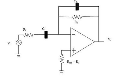
Differentiator Op Amp Circuit
The differentiator circuit is an application circuit derived from mathematical principles influenced by capacitor behavior. The circuit, as illustrated in the accompanying image, is a simple differentiator configuration. To derive the differentiator formula, the following sequence is used: Ic =...

Precision Full-Wave Rectifier
This circuit utilizes two operational amplifiers (op amps) to generate a full-wave rectified version of the input signal. Op amp IC1 inverts the negative-going signal, but due to diode D2, it remains close to zero. IC2 generates a positive-going signal....

Linear-ic-siren
A low-frequency op-amp oscillator and a voltage-controlled oscillator (VCO), both configured using a single MC3405 dual op-amp and dual comparator, are the primary components in a siren circuit capable of producing various warbles and wails, or functioning as an audio...

Single Capacitor Powers Audio Mixer
Micropower and low-voltage operational amplifiers enable the construction of high-performance analog signal processors that do not require batteries or wall transformers. Instead, a capacitor can serve as the power source. The circuit illustrated in Figure 1 depicts an analog mixer...

Check For Op-Amp Dc Offset Shift Circuit
The DC values of op-amp offsets cannot always be assumed to remain constant when delivering AC outputs. No device is perfectly symmetrical in terms of maximum positive slew rate compared to maximum negative slew rate. As a result, there exists...
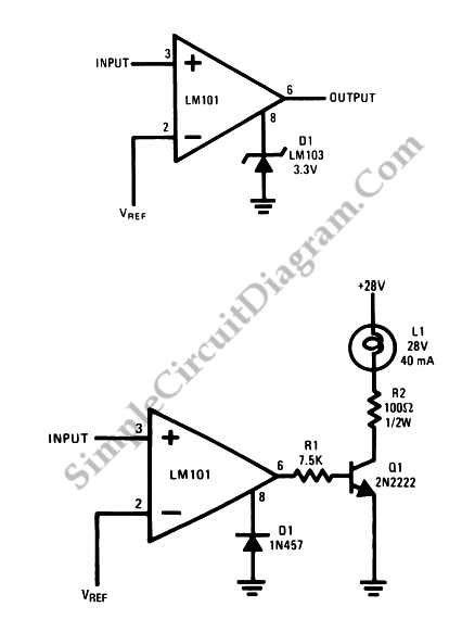
Op-Amp Application: Voltage Comparators
Two reasons why the LM101 is well-suited for comparator applications are its large differential input voltage range and the ease of clamping the output.
The LM101 operational amplifier is particularly advantageous for use in comparator circuits due to its significant differential...

Glitch-Free Clipper
A simple clamping circuit can be added to a Harris 2620 high-speed operational amplifier (op-amp) to create a glitch-free amplifier and clipper. The pin that controls the device's bandwidth is a high-impedance, isolated input, which also tracks the output voltage...
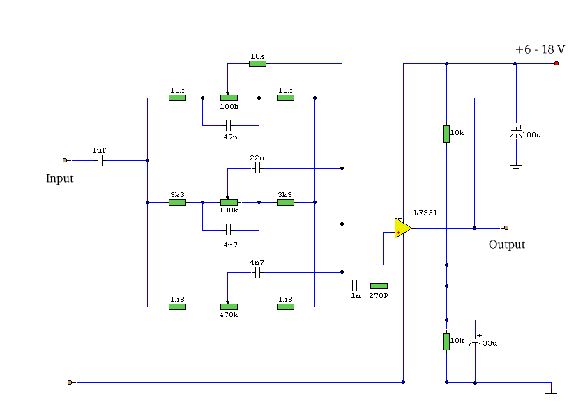
3 Band Graphic Equalizer
This simple equalizer circuit utilizes a single operational amplifier (op-amp) to provide three distinct frequency ranges: low frequency, mid frequency, and high frequency. With the specified component values, the circuit is capable of delivering an approximate gain of +/-20dB at...