


Telephone blinker

Description: A small neon lamp is activated by the telephone's ringing voltage, allowing a sufficient current to flow to the LED in optocoupler U1. This activation subsequently triggers a 6-A Triac that controls a 117-Vac lamp or bell. Capacitor C1 is only required when the circuit is utilized to drive a bell. The lamp will flash on and off at the ringing rate, which typically is around 20 Hz. If a 117-Vac bell is employed, it should be connected in place of the lamp.
The described circuit utilizes a neon lamp as a voltage sensing element that responds to the alternating current (AC) ringing voltage generated by a telephone line. When the phone rings, the neon lamp turns on, allowing current to flow through the LED of optocoupler U1. The optocoupler serves as an isolation barrier, transferring the signal from the low-voltage side to the high-voltage side without direct electrical connection.
The LED within the optocoupler, upon receiving current from the neon lamp, illuminates and triggers the phototransistor inside the optocoupler. This action causes the phototransistor to conduct, effectively closing a switch that activates the gate of the Triac. The Triac is a semiconductor device capable of controlling AC power, and in this configuration, it is rated for 6 Amperes, suitable for driving loads such as a 117-Vac lamp or bell.
In cases where a bell is used instead of a lamp, capacitor C1 is included in the circuit to provide necessary phase shift and stabilization for the Triac operation. The flashing of the lamp or bell occurs at the ringing frequency of the telephone, approximately 20 Hz, creating a visual or audible indication of an incoming call.
To implement this circuit effectively, proper attention must be given to component ratings, ensuring that the Triac can handle the load current and voltage, and that the optocoupler is rated for the necessary isolation voltage. Additionally, the neon lamp should be selected based on its breakdown voltage characteristics to ensure reliable triggering at the ringing voltage. Overall, this circuit provides a simple and effective means to indicate telephone ringing through visual or audible alerts.A small neon lamp is triggered into conduction by the telephone's ringing voltage, passes just enough current to activate the LED in optocoupler Ul, which in turn triggers the 6-A Triac that controls 12—a 117-Vac lamp or bell. (Capacitor Cl is necessary only when the circuit is used to drive a bell.) The lamp will flash off-and-on at the ringing rate, which is normally around 20 Hz.
Ha 117 Vac bell is used, connect it in place of the lamp.
The described circuit utilizes a neon lamp as a voltage sensing element that responds to the alternating current (AC) ringing voltage generated by a telephone line. When the phone rings, the neon lamp turns on, allowing current to flow through the LED of optocoupler U1. The optocoupler serves as an isolation barrier, transferring the signal from the low-voltage side to the high-voltage side without direct electrical connection.
The LED within the optocoupler, upon receiving current from the neon lamp, illuminates and triggers the phototransistor inside the optocoupler. This action causes the phototransistor to conduct, effectively closing a switch that activates the gate of the Triac. The Triac is a semiconductor device capable of controlling AC power, and in this configuration, it is rated for 6 Amperes, suitable for driving loads such as a 117-Vac lamp or bell.
In cases where a bell is used instead of a lamp, capacitor C1 is included in the circuit to provide necessary phase shift and stabilization for the Triac operation. The flashing of the lamp or bell occurs at the ringing frequency of the telephone, approximately 20 Hz, creating a visual or audible indication of an incoming call.
To implement this circuit effectively, proper attention must be given to component ratings, ensuring that the Triac can handle the load current and voltage, and that the optocoupler is rated for the necessary isolation voltage. Additionally, the neon lamp should be selected based on its breakdown voltage characteristics to ensure reliable triggering at the ringing voltage. Overall, this circuit provides a simple and effective means to indicate telephone ringing through visual or audible alerts.A small neon lamp is triggered into conduction by the telephone's ringing voltage, passes just enough current to activate the LED in optocoupler Ul, which in turn triggers the 6-A Triac that controls 12—a 117-Vac lamp or bell. (Capacitor Cl is necessary only when the circuit is used to drive a bell.) The lamp will flash off-and-on at the ringing rate, which is normally around 20 Hz.
Ha 117 Vac bell is used, connect it in place of the lamp.

Telephone line monitor circuit
This compact circuit enables automatic recording of phone conversations. It connects to the phone line, the microphone input of a tape recorder, and the remote control jack of the recorder. The circuit detects the voltage level in the phone line...

ac Validate Triac circuit
The heatsink on the triac is somewhat unclear. A maximum value of 10°C/W has been calculated, which raises concerns. The calculation is as follows: (maximum temperature - room temperature) / (maximum on-stage voltage * (milliamps / voltage) - junction-to-base thermal...
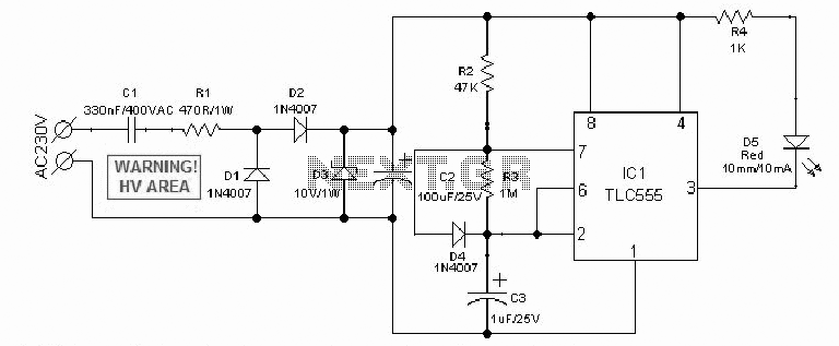
Power 220V LED Flashing
An AC mains operated single LED flasher circuit is designed using the widely used CMOS timer chip TLC555. The entire circuit is powered directly by the grid supply of 230VAC through a capacitive potential divider and associated components.
This LED flasher...

7Segment Common LED UV Exposure Box
7-Segment Common LED UV Exposure Box Circuit Diagram. Features: Utilizes Stan Ocker's circuit design, employing a PIC16F84 microcontroller to count and display the time.
The 7-Segment Common LED UV Exposure Box Circuit is designed for applications requiring precise timing and display...

Simple power Supply for LEDS
LEDs are great display tools. Their prices have decreased to a point where they are replacing more conventional light sources. In one sense, their characteristic need for low voltages is an advantage, e.g., compatibility with I.C. drives, but this voltage...

simple current controlled led tube
The circuit of a current-controlled LED tube light employs high-voltage transistors to implement the necessary current control operation based on a fundamental principle. A resistor (R2) is utilized to convert the increasing current into a voltage across itself. This voltage...
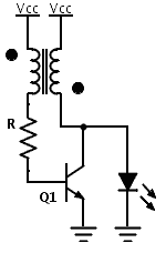
LED Boost converter Joule Thief circuit
Previously, a boost circuit was tested that enables the powering of a 3 V LED using a discharged battery (approximately 1 V or lower). This circuit consists of a single transistor, one resistor, and a small transformer with a 1:1...

LED VU Meter by LM339 PCB
The circuit utilizes two quad voltage comparators (LM339) to illuminate a series of eight LEDs that indicate volume levels. Each of the eight comparators is set to specific bias voltages determined by a voltage divider, allowing the lower right LED...

Triac lamp dimmer
A heatsink allows the TRIAC (TR1) to manage a maximum power of 350 watts. The neon lamp, II, will not activate the gate until the TRIAC begins conducting, and resistor R1 can be adjusted to set the desired lighting level.
The...