


ultrasonic rat repellent
#ultrasonic
#rat repellent
#pest control
#sound frequency
#animal deterrent
#sensor
#audio
#home automation
#security

Description: Ultrasonic rat repellent circuit and notes on ultrasonic experiments on rats.
The ultrasonic rat repellent circuit is designed to emit high-frequency sound waves that are above the range of human hearing but can be detected by rodents. These sound waves are intended to create an uncomfortable environment for rats, thereby driving them away from the area where the circuit is deployed.
The circuit typically consists of the following key components:
1. **Ultrasonic Transducer**: This component converts electrical signals into ultrasonic sound waves. It operates at frequencies usually between 20 kHz and 65 kHz, which are effective in repelling rodents.
2. **Oscillator Circuit**: An oscillator is used to generate the high-frequency signal that drives the transducer. This can be implemented using a 555 timer IC configured in astable mode or a microcontroller that can output PWM signals at the desired frequency.
3. **Power Supply**: The circuit requires a suitable power supply, which can be a battery or an AC adapter, depending on the design. The power supply should be capable of providing sufficient current to the transducer for effective operation.
4. **Amplifier (optional)**: In some designs, an amplifier may be included to boost the output signal from the oscillator before it reaches the transducer, ensuring that the ultrasonic waves are emitted at a higher intensity.
5. **Control Circuit**: Some advanced circuits may include a control mechanism that allows for adjusting the frequency or duration of the ultrasonic sound waves. This can enhance the effectiveness of the repellent by varying the output to prevent rodents from becoming accustomed to a constant frequency.
The circuit layout should be designed to minimize interference and optimize the performance of the ultrasonic transducer. Proper placement of the transducer is crucial; it should be positioned in an area where rats are likely to pass through while ensuring that the sound waves can propagate effectively without significant obstructions.
In addition to the circuit design, notes on ultrasonic experiments with rats may include observations on the effectiveness of different frequencies, the duration of exposure, and the behavioral responses of rodents to the ultrasonic sounds. These experiments can provide valuable insights into optimizing the circuit for maximum repellent efficacy.Ultrasonic Rat Repellent circuit and Notes on ultrasonic experiments on rats..
The ultrasonic rat repellent circuit is designed to emit high-frequency sound waves that are above the range of human hearing but can be detected by rodents. These sound waves are intended to create an uncomfortable environment for rats, thereby driving them away from the area where the circuit is deployed.
The circuit typically consists of the following key components:
1. **Ultrasonic Transducer**: This component converts electrical signals into ultrasonic sound waves. It operates at frequencies usually between 20 kHz and 65 kHz, which are effective in repelling rodents.
2. **Oscillator Circuit**: An oscillator is used to generate the high-frequency signal that drives the transducer. This can be implemented using a 555 timer IC configured in astable mode or a microcontroller that can output PWM signals at the desired frequency.
3. **Power Supply**: The circuit requires a suitable power supply, which can be a battery or an AC adapter, depending on the design. The power supply should be capable of providing sufficient current to the transducer for effective operation.
4. **Amplifier (optional)**: In some designs, an amplifier may be included to boost the output signal from the oscillator before it reaches the transducer, ensuring that the ultrasonic waves are emitted at a higher intensity.
5. **Control Circuit**: Some advanced circuits may include a control mechanism that allows for adjusting the frequency or duration of the ultrasonic sound waves. This can enhance the effectiveness of the repellent by varying the output to prevent rodents from becoming accustomed to a constant frequency.
The circuit layout should be designed to minimize interference and optimize the performance of the ultrasonic transducer. Proper placement of the transducer is crucial; it should be positioned in an area where rats are likely to pass through while ensuring that the sound waves can propagate effectively without significant obstructions.
In addition to the circuit design, notes on ultrasonic experiments with rats may include observations on the effectiveness of different frequencies, the duration of exposure, and the behavioral responses of rodents to the ultrasonic sounds. These experiments can provide valuable insights into optimizing the circuit for maximum repellent efficacy.Ultrasonic Rat Repellent circuit and Notes on ultrasonic experiments on rats..

Ultrasonic range finder circuit
The circuit is designed to be low cost. It uses a PIC12C508 to perform the control functions and standard 40 kHz piezo transducers. The drive to the transmitting transducer can be simply driven directly from the PIC. The 5V drive...

Ultrasonic Pest Repeller
A higher-end version of the same device, featuring additional user-selectable settings to enable both audible and ultrasonic output, enhancing its effectiveness against animals.
The described device is an advanced electronic system designed to produce sound waves at both audible and ultrasonic...

Audio peak Indicator
This circuit can be used to remotely monitor a loudspeaker, alarm, or audio source for presence of an audio waveform. It can also be directly connected across loudspeaker terminals used as a peak indicator. If you need to monitor some...
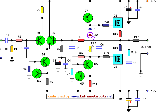
60 Watt Audio Power Amplifier
In the original circuit, a series of three diodes was connected to resistor R10. Two of these diodes have been replaced with a red LED to enhance quiescent current stability across a broader temperature range. This modification was suggested by...

Ultrasonic atomizer 2
The ultrasonic atomizer circuit consists of a power supply circuit, control circuit, water detection alarm circuit, and an ultrasonic oscillator, as illustrated in Figure 3-190. The power supply circuit includes a power switch (S), fuses (FU1, FU2), a timer (Q),...

Ultrasonic-receiver
The 4046 PLL is utilized as the core component of a tunable ultrasonic receiver designed for detecting inaudible ultrasonic sounds. This receiver can also function in conjunction with a simple ultrasonic generator to transmit and receive Morse code. The incoming...

ultrasonic transmitter 40khz
A 40kHz ultrasonic transmitter circuit consists of three oscillators (F1, F2, and F3), with F3 generating a 40kHz square wave output. The frequency is primarily determined by components C1, R1, and an adjustable resistor (RP). The excitation output from the...

Car stereo amplifier based TDA1535
The provided schematic represents a car stereo amplifier circuit that can be utilized in cars or other vehicles. The circuit is based on the TDA1553, which is a Class-B audio amplifier. This circuit is straightforward, consisting solely of the integrated...

Medical ultrasonic atomizer 2
The medical ultrasonic atomizer circuit consists of a power supply circuit, an atomization amount liquid level detection control circuit, an ultrasonic oscillator, and a fan motor (M). The power supply circuit includes a timer (Q), fuses (FU1, FU2), a power...