


100W FM Linear Amplifier
#FM amplifier
#linear amplifier
#RF circuits
#bipolar transistor
#MRF317
#C class bias
#low pass filter
#VSWR
#power amplifier

Description: This power amplifier is equipped with a bipolar transistor, the famous MRF317. As in many FM amplifier applications, the power transistor is in a C class bias. All the impedance networks (input & output) have been determined by using the software: Mimp.EXE. A 9-element low pass filter ensures that we meet at least a 60 dB rejection from the carrier (RF simulation with RFSIM99). The FM amplifier has a 10 dB gain with a 60 to 65% efficiency. The input VSWR is around 1.4 and there's no problem reaching the maximum power in all the FM band.
The described power amplifier utilizes the MRF317 bipolar transistor, which is well-regarded for its performance in RF applications, particularly in FM broadcasting. The Class C biasing configuration employed in this circuit is optimal for high-efficiency applications, as it allows the transistor to conduct for less than half of the input signal cycle, thereby maximizing power output while minimizing heat generation.
The impedance matching networks for both the input and output stages are crucial for ensuring maximum power transfer and minimizing signal reflection. These networks have been designed using Mimp.EXE software, which aids in the precise calculation of component values to achieve the desired frequency response. The inclusion of a 9-element low pass filter at the output stage is particularly noteworthy, as it serves to attenuate unwanted harmonics and spurious signals, ensuring compliance with regulatory standards by providing at least 60 dB of rejection from the carrier frequency. The RF simulation performed with RFSIM99 further validates the design, allowing for adjustments based on simulated performance metrics.
The amplifier's gain of 10 dB indicates a substantial increase in signal strength, making it suitable for various FM transmission applications. The efficiency rating of 60 to 65% suggests that a significant portion of the input power is converted into useful output power, which is a critical factor in the design of power amplifiers to reduce operational costs and thermal management issues.
The input Voltage Standing Wave Ratio (VSWR) of approximately 1.4 indicates good impedance matching, which minimizes reflections and maximizes power delivery from the source to the amplifier. This characteristic is essential for maintaining the integrity of the transmitted signal across the entire FM band, ensuring that the amplifier can operate effectively without distortion or loss of quality.
Overall, this power amplifier design is well-suited for FM broadcasting applications, providing a balance of efficiency, gain, and signal integrity.This Power amplifier is equiped with a bipolar transistor,the famous MRF317. As lots of FM amplifier application ,the power transistor is in a C class bias. All the impedance networks (Input & Output) have been determined by using the software: Mimp.EXE. A 9 elements low pass filter ensures that we meet at least a 60 dB rejection from the carrier.(RF Simulation with RFSIM99). The FM amplifier has a 10 dB gain with a 60 to 65% efficiency. The Input VSWR is around 1.4 and there's no problem to reach the max power in all the FM band..
The described power amplifier utilizes the MRF317 bipolar transistor, which is well-regarded for its performance in RF applications, particularly in FM broadcasting. The Class C biasing configuration employed in this circuit is optimal for high-efficiency applications, as it allows the transistor to conduct for less than half of the input signal cycle, thereby maximizing power output while minimizing heat generation.
The impedance matching networks for both the input and output stages are crucial for ensuring maximum power transfer and minimizing signal reflection. These networks have been designed using Mimp.EXE software, which aids in the precise calculation of component values to achieve the desired frequency response. The inclusion of a 9-element low pass filter at the output stage is particularly noteworthy, as it serves to attenuate unwanted harmonics and spurious signals, ensuring compliance with regulatory standards by providing at least 60 dB of rejection from the carrier frequency. The RF simulation performed with RFSIM99 further validates the design, allowing for adjustments based on simulated performance metrics.
The amplifier's gain of 10 dB indicates a substantial increase in signal strength, making it suitable for various FM transmission applications. The efficiency rating of 60 to 65% suggests that a significant portion of the input power is converted into useful output power, which is a critical factor in the design of power amplifiers to reduce operational costs and thermal management issues.
The input Voltage Standing Wave Ratio (VSWR) of approximately 1.4 indicates good impedance matching, which minimizes reflections and maximizes power delivery from the source to the amplifier. This characteristic is essential for maintaining the integrity of the transmitted signal across the entire FM band, ensuring that the amplifier can operate effectively without distortion or loss of quality.
Overall, this power amplifier design is well-suited for FM broadcasting applications, providing a balance of efficiency, gain, and signal integrity.This Power amplifier is equiped with a bipolar transistor,the famous MRF317. As lots of FM amplifier application ,the power transistor is in a C class bias. All the impedance networks (Input & Output) have been determined by using the software: Mimp.EXE. A 9 elements low pass filter ensures that we meet at least a 60 dB rejection from the carrier.(RF Simulation with RFSIM99). The FM amplifier has a 10 dB gain with a 60 to 65% efficiency. The Input VSWR is around 1.4 and there's no problem to reach the max power in all the FM band..

100W 420-450Mhz push-pull linear amplifier
This 100-watt linear amplifier can be built using two MRF309 transistors in a push-pull configuration, requiring only 16 watts of drive power within the frequency range of 420 to 450 MHz. It operates from a 28-volt supply and achieves eight...

Composite CPI amplifier
B is a pure output Class B mode power amplifier. The preamplifier input section of the circuit does not utilize a conventional differential input circuit; instead, it employs a single-ended input. This design features a single-ended output Composite CPI, which...

Low pass filter for Subwoofers
In the form it appears the theoretical circuit of filter. In first glance we see three different circuits that are mainly manufactured round two operational amplifiers. This circuits constitute mixed, amplifier with variable aid and a variable filter. The manufacture...

The same capacitance parameters easy to change the cutoff frequency of the low pass filter 24dB-oct
A 24 dB/octave Butterworth filter with a maximally flat characteristic is constructed using two filters, each capable of providing a 12 dB/octave response. This configuration allows for a 3 dB point adjustment. To achieve the desired cutoff frequency, adjustments are...

Pre-dividing power amplifier
An active high-power tube operates in the MHz range, priced around 3 to 4 yuan, with a transition frequency (fT) exceeding one-fifth of 50 MHz for similar power tubes. This circuit is designed for high reliability in low-frequency high-power amplifier...

Amp Circlotron
It is a power amplifier configuration developed in the 1950s, known as a circlotron due to its original diagram being drawn in a circular shape. The best representation available is a bridge format. Its primary advantage is very low distortion....
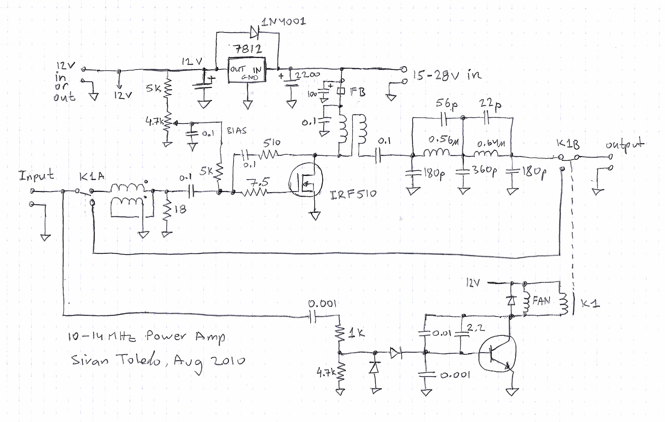
a 16w linear amplifier
The Softrock Ensemble RXTX has a 1W output, which is relatively low, so a linear amplifier was constructed to enhance the signal. This amplifier provides 16W output when supplied with a 24V power source (utilizing a 45W switching adapter from...

Power Amplifier 6
This simple circuit is designed to provide an output power of approximately 1 watt when connected to a 9-volt power supply. The key advantage of this circuit is its use of a dual Darlington configuration, which increases the input impedance...
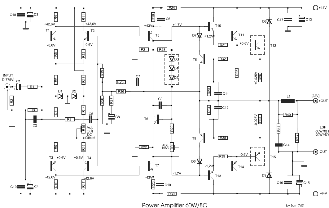
power amplifier 60w8
This circuit was designed and manufactured in the 1980s. Since then, it has operated without issues. There are no significant constructional challenges, aside from the usual considerations: ensuring the appropriate power supply voltage, selecting a suitable heatsink, and properly matching...