


10W 10M Linear Amplifier Circuit
#linear amplifier
#10W amplifier
#10 meter band
#broadband transformers
#toroidal core
#PEP output
#RF amplifier
#bifilar windings
#RC feedback

Description: This linear amplifier provides a 10-W PEP output with a 1.25-W drive on the 10 m band. The transformers, T1, T2, and T3, consist of 10 turns of bifilar windings on an FT-50-43 toroidal core and are designed for broadband operation. Additional filters for other frequency bands can be implemented as needed. It is recommended to use #26 wire for capacitors C1 and C2, and to select capacitors that closely match the suggested values. As the operating frequency decreases, gain will increase, which may lead to instability; RC feedback may be necessary to mitigate this issue. The values referenced in the above table were sourced from the QRP Notebook by Doug DeMaw.
This linear amplifier circuit is designed to operate efficiently within the 10-meter amateur radio band, delivering a peak envelope power (PEP) output of 10 watts. The initial drive requirement is relatively low at 1.25 watts, making it suitable for low-power applications. The use of bifilar windings in the transformers T1, T2, and T3, wound on an FT-50-43 toroidal core, enhances the amplifier's ability to function across a broad frequency range, minimizing losses and improving overall performance.
The circuit layout should incorporate additional filters for other amateur radio bands if the operator desires multi-band functionality. These filters can be designed using standard LC filter topologies, ensuring that unwanted harmonics and spurious emissions are effectively attenuated while allowing the desired signals to pass through.
For capacitors C1 and C2, the recommendation to use #26 wire is crucial for maintaining the integrity of the circuit and ensuring minimal parasitic inductance. The choice of capacitors should be made carefully, selecting components that are as close as possible to the specified values to maintain the desired bandwidth and performance characteristics.
It is important to note that as the operating frequency of the amplifier decreases, there is a corresponding increase in gain. This phenomenon can lead to potential instability within the amplifier circuit. To counteract this effect, the implementation of RC feedback is advisable. This feedback mechanism can help stabilize the amplifier by reducing gain at lower frequencies, thereby ensuring consistent performance without oscillation or distortion.
The values utilized in this design have been referenced from the QRP Notebook by Doug DeMaw, which serves as a valuable resource for amateur radio enthusiasts and engineers alike, providing tested and proven designs for low-power RF applications. This linear amplifier delivers 10-W PEP output; with 1.25-W drive on 10 m. Tl, T2, and T3 are 10 turns of bifilar windings on an FT-50-43 toroidal core. The transformers are broadband. Filters for other bands, if desired, are shown. Note: use #26 wire for C1 and C2. Use capacitors that are closest to these suggested values. As the operating frequency decreases, the gain will Increase as well as the possibility for instability. You may have to use RC feedback to negate this effect. Values for the above table were obtained from the QRP Notebook by Doug DeMaw.
This linear amplifier circuit is designed to operate efficiently within the 10-meter amateur radio band, delivering a peak envelope power (PEP) output of 10 watts. The initial drive requirement is relatively low at 1.25 watts, making it suitable for low-power applications. The use of bifilar windings in the transformers T1, T2, and T3, wound on an FT-50-43 toroidal core, enhances the amplifier's ability to function across a broad frequency range, minimizing losses and improving overall performance.
The circuit layout should incorporate additional filters for other amateur radio bands if the operator desires multi-band functionality. These filters can be designed using standard LC filter topologies, ensuring that unwanted harmonics and spurious emissions are effectively attenuated while allowing the desired signals to pass through.
For capacitors C1 and C2, the recommendation to use #26 wire is crucial for maintaining the integrity of the circuit and ensuring minimal parasitic inductance. The choice of capacitors should be made carefully, selecting components that are as close as possible to the specified values to maintain the desired bandwidth and performance characteristics.
It is important to note that as the operating frequency of the amplifier decreases, there is a corresponding increase in gain. This phenomenon can lead to potential instability within the amplifier circuit. To counteract this effect, the implementation of RC feedback is advisable. This feedback mechanism can help stabilize the amplifier by reducing gain at lower frequencies, thereby ensuring consistent performance without oscillation or distortion.
The values utilized in this design have been referenced from the QRP Notebook by Doug DeMaw, which serves as a valuable resource for amateur radio enthusiasts and engineers alike, providing tested and proven designs for low-power RF applications. This linear amplifier delivers 10-W PEP output; with 1.25-W drive on 10 m. Tl, T2, and T3 are 10 turns of bifilar windings on an FT-50-43 toroidal core. The transformers are broadband. Filters for other bands, if desired, are shown. Note: use #26 wire for C1 and C2. Use capacitors that are closest to these suggested values. As the operating frequency decreases, the gain will Increase as well as the possibility for instability. You may have to use RC feedback to negate this effect. Values for the above table were obtained from the QRP Notebook by Doug DeMaw.

Circuit RF Amplifier
One of the most notable RF amplifiers documented is Wes Hayward's post-mixer amplifier in the Progressive Communications Receiver. It is recognized as a highly effective high-level RF amplifier, operating with a standing current of 50 mA, which allows it to...

70MHz RF FM Power Amplifier
This 70 MHz RF power amplifier circuit utilizes the SD1143 transistor, which offers a gain of approximately 14 dB in this configuration. The design leverages the characteristics of a 175 MHz device.
The RF power amplifier circuit designed around the SD1143...

Crystal Radio RF Amplifier
The circuit presented is a straightforward yet efficient amplifier that can provide notable performance enhancements. This amplifier can demonstrate negative resistance at lower settings of the 500-ohm potentiometer, resulting in increased gain or even oscillation. Consequently, the circuit can be...
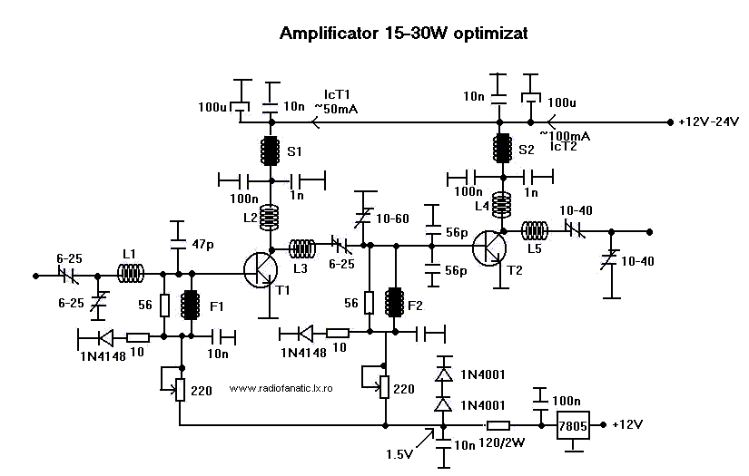
15W - 30W RF Power Amplifier KT922 KT930 KT934
This RF amplifier ensures the power required to boost a small transmitter. Depending on the input RF power, power supply, and transistor, this amplifier can boost the signal.
The RF amplifier is a critical component in various communication systems, designed to...

RF isolation amplifier
This wideband RF isolation amplifier has a frequency response of 0.5 to 400 MHz ± 0.5 dB. This two-stage amplifier can be utilized in applications that require high reverse isolation, such as receiver intermediate-frequency (IF) strips and frequency distribution systems....

and filter 1 3 5w power rf amplifier
An RF force amplifier for FM is essential for amateurs looking to enhance small transmitters, whether they are homemade or commercially available. The presented circuit can deliver 50-60W of RF power with an input control of 15-20W within the FM...
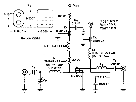
135-175Mhz amplifier
Cl. C2 ARCO #462, 2 to 60 pF, trimmer capacitors Li, 3 turns of #20 AWG wire on 1/4" diameter L2, β turns of #20 AWG on 1/4" diameter Ti. Additionally, there is 1 turn of 25 Ω coax on...

Wide band 10MHz 500MHz RF amplifier
This paper describes an RF amplifier circuit which is suitable for the frequencies between 10MHz and 500MHz. These kind of amplifiers are called wide band amplifiers. Wide band amplifiers are used in communication receivers, RF measuring equipment and tons of...

2-30Mhz-amplifier
This amplifier delivers a nominal output power of 140 watts peak envelope power (PEP) when fed with input levels as low as 3 watts. Both the input and output transformers feature a 4:1 turn ratio and a 16:1 impedance ratio,...