


20 Watt Power Amplifier with TDA2005
#TDA2005
#power amplifier
#20 watt
#automotive
#bridge configuration
#2 ohm speaker
#14.4 volts
#short circuit protection
#thermal protection

Description: This IC chip was designed specifically for use in power boosting applications in automobiles. It is self protecting against short circuits and thermal problems. In the bridge configuration shown it will deliver 20 watts of power into a 2 ohm speaker operating at 14.4 volts.
The integrated circuit (IC) chip referenced is optimized for automotive power amplification, making it suitable for driving speakers in vehicle audio systems. The design incorporates advanced protection mechanisms, allowing it to withstand short circuits and prevent thermal overload, which enhances reliability in automotive environments where conditions can be variable and demanding.
In a bridge configuration, this IC can efficiently deliver an output power of 20 watts into a load of 2 ohms. The bridge configuration typically involves connecting two amplifying devices in such a way that they drive the speaker with opposite phases of the input signal, effectively doubling the output voltage across the speaker. This configuration not only maximizes power output but also improves the overall efficiency of the audio system.
The operational voltage of 14.4 volts is standard for automotive applications, as it corresponds to the nominal voltage of a vehicle's electrical system when the engine is running. This makes the IC suitable for direct integration into automotive audio systems without the need for additional voltage regulation components.
To ensure optimal performance, the circuit design should include appropriate filtering capacitors to stabilize the power supply and minimize noise. Additionally, heat dissipation mechanisms, such as heat sinks or thermal pads, should be implemented to manage the heat generated during operation, especially at higher output levels.
Overall, this IC chip represents a robust solution for enhancing audio performance in automotive applications, combining power efficiency with protective features essential for reliability in mobile environments.This IC chip was designed specifically for use in power boosting applications in automobiles. It is self protecting against short circuits and thermal problems. In the bridge configuration shown it will deliver 20 watts of power into a 2 ohm speaker operating at 14.4 volts.
The integrated circuit (IC) chip referenced is optimized for automotive power amplification, making it suitable for driving speakers in vehicle audio systems. The design incorporates advanced protection mechanisms, allowing it to withstand short circuits and prevent thermal overload, which enhances reliability in automotive environments where conditions can be variable and demanding.
In a bridge configuration, this IC can efficiently deliver an output power of 20 watts into a load of 2 ohms. The bridge configuration typically involves connecting two amplifying devices in such a way that they drive the speaker with opposite phases of the input signal, effectively doubling the output voltage across the speaker. This configuration not only maximizes power output but also improves the overall efficiency of the audio system.
The operational voltage of 14.4 volts is standard for automotive applications, as it corresponds to the nominal voltage of a vehicle's electrical system when the engine is running. This makes the IC suitable for direct integration into automotive audio systems without the need for additional voltage regulation components.
To ensure optimal performance, the circuit design should include appropriate filtering capacitors to stabilize the power supply and minimize noise. Additionally, heat dissipation mechanisms, such as heat sinks or thermal pads, should be implemented to manage the heat generated during operation, especially at higher output levels.
Overall, this IC chip represents a robust solution for enhancing audio performance in automotive applications, combining power efficiency with protective features essential for reliability in mobile environments.This IC chip was designed specifically for use in power boosting applications in automobiles. It is self protecting against short circuits and thermal problems. In the bridge configuration shown it will deliver 20 watts of power into a 2 ohm speaker operating at 14.4 volts.

100W + 100W power amplifier
As illustrated in Figure 3-30, the IC LA4425 power amplifier stage is utilized alongside a pair of power module 1490 configured for push-pull output. This setup functions as an impedance converter, enabling the system to deliver 100 watts of output...

20 Watt Power Amplifier
A 20 Watt car power amplifier circuit diagram based on the TDA 2005. The TDA 2005 IC is specifically designed for power boosting applications in car audio systems. This IC includes protection against short circuits and overheating. The circuit utilizes...

short circuit protection for balanced
This circuit was designed to protect a dual rail power supply from shorts across the two rails. It uses an optocoupler to monitor each supply rail, with the internal LEDs powered from ZD2 and ZD3 and the associated resistors. While...
Power Amplifier Theory for High-Efficiency Low-Cost ISM-Band Transmitters
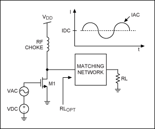
This application note provides a concise overview of power amplifier theory and presents simulation results that offer insights into the operation of the power amplifier across all of MAXIM's LFRF transmitters and transceivers.
Power amplifiers are critical components in communication systems,...

Voltage Regulator For Cars And Motorcycles
This regulator circuit can be used on an alternator that has one field terminal grounded. When the input voltage becomes too high, Q1 conducts, and the base of Q2 is driven toward ground, reducing the voltage fed to Q3. This...

150W Power Amplifier
A 150W power amplifier circuit diagram utilizing power transistors TIP41, TIP142, and TIP147. The design is straightforward enough to construct without a printed circuit board (PCB). The power output range is approximately 100-150W.
The 150W power amplifier circuit is designed to...

Walkman splice power production circuit
The first power amplifier circuit illustrated in Figure 5-88 utilizes the NE5532 operational amplifier, configured as a line amplifier, and features the TDA1521 power amplifier. This circuit operates with a dual power supply and eliminates the need for coupling capacitors,...

simplest smf automotive battery charger
A simple battery charger circuit is described, utilizing a single transistor for voltage detection and automatically disconnecting the battery from the supply when fully charged. The circuit's high voltage trip point is set to switch off the charging voltage when...

Bridging Adapter For Power Amplifiers
A stereo power amplifier is limited in its output power by two main factors - the impedance of the load and the internal power supply voltage. To obtain more power, one has very limited choices - other than the purchase...