


50WOTL amplifier circuit
#OTL amplifier
#50W
#audio amplifier
#frequency response
#high power
#sound system
#electronics
#DIY amplifier
#audio circuit

Description: The circuit depicted in the figure is a highly technical OTL (Output Transformer-Less) amplifier circuit. It features a frequency response range of 10 Hz to 100 kHz and exhibits a total harmonic distortion of less than 0.1%, which is considered minimal. The YFL power amplifier consists of four main sections: the input stage, the impedance converter stage, the power output stage, and the inverter stage. The circuit employs interstage resistance and capacitance coupling units without large DC negative feedback loops. Instead, local feedback is utilized at each stage to maintain a stable operating point. The circuit is designed with a fixed operating point at O VTi and includes peripheral components in the input stage to enhance circuit stability and input impedance. The emitter resistor (R1) of O VT2 is a high-value resistor, approximately 1.5 kΩ. The input stage, consisting of direct-coupled amplifiers VT2 and VT3, is coupled through capacitor C3. The R1 resistor provides negative feedback to stabilize the operating point of the circuit. The emitter output of VT3 is utilized to lower the output impedance, facilitating a better match for the inverter stage VT4 and improving its push capability.
The OTL amplifier circuit is designed for high fidelity and low distortion audio amplification, making it suitable for high-end audio applications. The frequency response range of 10 Hz to 100 kHz allows it to reproduce a wide spectrum of audio frequencies, ensuring that both low and high frequencies are accurately amplified. The low total harmonic distortion (THD) of less than 0.1% indicates that the amplifier can deliver a clean and accurate audio signal, minimizing unwanted artifacts that can affect sound quality.
The circuit's architecture is divided into four distinct stages, each serving a specific function. The input stage is responsible for receiving the audio signal and preparing it for further amplification. The impedance converter stage matches the input impedance to the subsequent stages, ensuring efficient signal transfer. The power output stage amplifies the signal to a level suitable for driving speakers, while the inverter stage serves to further enhance the output signal's characteristics.
The use of local feedback at each stage helps in maintaining stability and preventing oscillations, which can be a common issue in high-gain amplifier designs. By avoiding large DC negative feedback loops, the circuit retains its dynamic range and responsiveness, which is crucial for high-quality audio reproduction.
The choice of a high-value resistor in the emitter circuit of VT2 contributes to the overall stability and performance of the amplifier. This design decision helps to ensure that the operating point remains fixed, even with variations in input signal levels or component tolerances. The coupling capacitor (C3) plays a vital role in blocking DC while allowing AC signals to pass, ensuring that only the desired audio frequencies are amplified.
Finally, the output impedance reduction achieved through the emitter output of VT3 allows for better interaction with the load (speakers), improving the amplifier's overall performance and efficiency. This careful consideration of component values and circuit topology results in a robust OTL amplifier capable of delivering high-quality audio with minimal distortion.Circuit shown in Figure. Higher technical specifications of the circuit, is a very good OTL amplifier circuit. The frequency response of the circuit of 10Hz ~ 100kH, total harmonic distortion <0.1%, which is not much in general (YFL power amplifier see o barrier circuit consists of four parts: the input stage, impedance converter stage, and power output of the inverter stage level. interstage resistance and capacitance coupling units, no large DC negative feedback loop, since each level plus deeper local feedback, so the working point of the circuit is very stable fixed O VTi and peripheral components of the input stage, in order to increase the input impedance of the circuit and stability ,, rTc emitter using a high-value resistor 1_5kfl of O VT2, VT3 composed of direct-coupled amplifier input stage and it is coupled by a capacitor C3 o Rl l-oriented electrical negative feedback stage resistance, to stabilize the operating point of the level oVT3 using emitter output, to reduce the output impedance, easy and inverter stage VT4 match, improve inverter stage VT4 push capability.
The OTL amplifier circuit is designed for high fidelity and low distortion audio amplification, making it suitable for high-end audio applications. The frequency response range of 10 Hz to 100 kHz allows it to reproduce a wide spectrum of audio frequencies, ensuring that both low and high frequencies are accurately amplified. The low total harmonic distortion (THD) of less than 0.1% indicates that the amplifier can deliver a clean and accurate audio signal, minimizing unwanted artifacts that can affect sound quality.
The circuit's architecture is divided into four distinct stages, each serving a specific function. The input stage is responsible for receiving the audio signal and preparing it for further amplification. The impedance converter stage matches the input impedance to the subsequent stages, ensuring efficient signal transfer. The power output stage amplifies the signal to a level suitable for driving speakers, while the inverter stage serves to further enhance the output signal's characteristics.
The use of local feedback at each stage helps in maintaining stability and preventing oscillations, which can be a common issue in high-gain amplifier designs. By avoiding large DC negative feedback loops, the circuit retains its dynamic range and responsiveness, which is crucial for high-quality audio reproduction.
The choice of a high-value resistor in the emitter circuit of VT2 contributes to the overall stability and performance of the amplifier. This design decision helps to ensure that the operating point remains fixed, even with variations in input signal levels or component tolerances. The coupling capacitor (C3) plays a vital role in blocking DC while allowing AC signals to pass, ensuring that only the desired audio frequencies are amplified.
Finally, the output impedance reduction achieved through the emitter output of VT3 allows for better interaction with the load (speakers), improving the amplifier's overall performance and efficiency. This careful consideration of component values and circuit topology results in a robust OTL amplifier capable of delivering high-quality audio with minimal distortion.Circuit shown in Figure. Higher technical specifications of the circuit, is a very good OTL amplifier circuit. The frequency response of the circuit of 10Hz ~ 100kH, total harmonic distortion <0.1%, which is not much in general (YFL power amplifier see o barrier circuit consists of four parts: the input stage, impedance converter stage, and power output of the inverter stage level. interstage resistance and capacitance coupling units, no large DC negative feedback loop, since each level plus deeper local feedback, so the working point of the circuit is very stable fixed O VTi and peripheral components of the input stage, in order to increase the input impedance of the circuit and stability ,, rTc emitter using a high-value resistor 1_5kfl of O VT2, VT3 composed of direct-coupled amplifier input stage and it is coupled by a capacitor C3 o Rl l-oriented electrical negative feedback stage resistance, to stabilize the operating point of the level oVT3 using emitter output, to reduce the output impedance, easy and inverter stage VT4 match, improve inverter stage VT4 push capability.

stereo power amplifier 4w 8w with tda2005
This circuit is a class AB stereo audio power amplifier designed by Quasar for high-fidelity applications using a TDA2005 module. It is straightforward to construct and requires a minimal number of external components. The module includes output current protection and...

TBA820M high gain audio amplifier circuit design electronic project
A very simple audio amplifier circuit can be designed using the TBA820M audio amplifier integrated circuit with just a few electronic components. This audio amplifier project features a high gain that allows for the detection of sounds underwater. The TBA820M...

Bypassing tone controls from Dyna Pas preamp
Inquiring about a simple method to bypass the tone controls in the preamplifier, with the understanding that a feedback circuit may be involved, leading to uncertainty.
To bypass the tone controls in a preamplifier, one common method is to modify the...

Circuit power audio amplifier stereo with LM1875 and preamp for NE5532 2 x 20 Watts
The LM1875 delivers 20 watts into a 4 or 8-ohm load on ±25V supplies. Using an 8-ohm load and ±30V supplies, over 30 watts of power may be delivered. The amplifier is designed to operate with a minimum of external...

Direct coupling audio power amplifier configuration A741 circuit
The direct coupling audio power amplifier utilizes an integrated operational amplifier. There are typically two practical configurations. The first configuration, depicted in (a), features a circuit structure that includes the output of the operational amplifier and a complementary symmetry emitter...
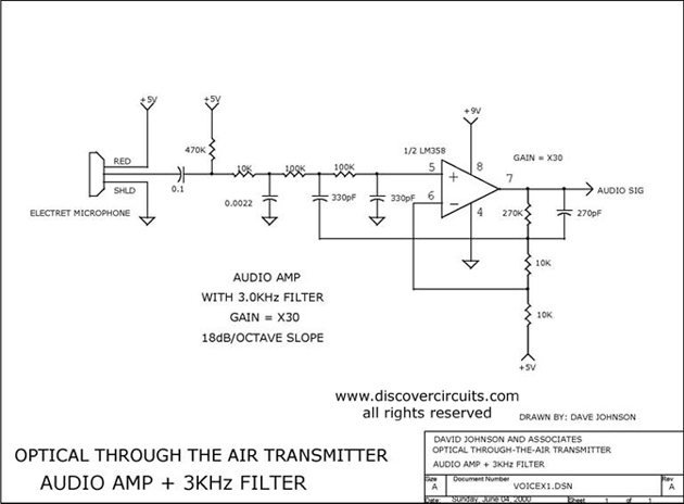
AUDIO AMP + 3KHz FILTER
Audio amplifier with a 3 kHz filter. This circuit serves as the audio amplification section for a complete optical transmitter. It amplifies and filters voice audio signals from an electret microphone.
The audio amplifier circuit is designed to enhance the weak...

TDA2030AL-TA5-T 18W Hi-Fi Audio Power Amplifier And 35W Driver
The TDA2549 is a complete intermediate frequency (IF) circuit that includes automatic frequency control (AFC), automatic gain control (AGC), demodulation, and video preamplification capabilities for multistandard television receivers. It can process both positively and negatively modulated video signals in color...

22 Watt Audio Amplifier
The 22 watt amp is easy to build, and very inexpensive. The circuit can be used as a booster in a car audio system, an amp for satellite speakers in a surround sound or home theater system, or as an...

Audio Power Amplifier Circuit
The circuit is designed around an LM741 operational amplifier configured as an inverting amplifier. It is utilized to drive complementary transistors (Q1 and Q2). The feedback loop of the op-amp incorporates the base-emitter junctions of both transistors, which aids in...