


A double-tuned amplifier circuit
#double-tuned amplifier
#resonant circuits
#transformer
#primary coil
#secondary coil
#parallel resonance
#RF amplifier
#signal amplification
#tuned circuit

Description: There are two resonant circuits in a double-tuned amplifier circuit, which consists of transformers T1 and T2 with primary and secondary coils that include parallel resonance capacitors. This circuit exhibits a resonance function and can be classified based on the coupling type into mutual coupling and capacitive coupling. Figure 3-20 illustrates this concept. Figure (a) depicts the mutual inductance coupling double-tuned amplifier, which is similar to a single-tuned amplifier but utilizes inductors L1 and C3 in place of a single secondary winding. The mutual coupling between the primary and secondary coils can be altered by changing the distance between L1 and L2. Figure (b) illustrates the capacitive coupling amplifier, where the degree of coupling is modified by adjusting an external capacitor Ck between the two tuners.
The double-tuned amplifier circuit is a specialized electronic configuration that enhances signal amplification by utilizing two resonant circuits. Each resonant circuit is designed to resonate at a specific frequency, allowing for improved selectivity and gain at that frequency. The transformers T1 and T2 serve as the core components of this configuration, with their primary and secondary coils strategically arranged to achieve the desired coupling effect.
The mutual coupling configuration, as depicted in Figure (a), relies on the magnetic interaction between the inductors. By adjusting the physical separation between inductors L1 and L2, the mutual inductance can be varied, thereby influencing the overall coupling coefficient. This adjustment enables fine-tuning of the amplifier's frequency response, allowing it to selectively amplify signals at the resonant frequency while attenuating others. The use of capacitors, such as C3, in conjunction with the inductors further refines the tuning process, ensuring that the amplifier operates efficiently within its intended frequency range.
On the other hand, the capacitive coupling configuration illustrated in Figure (b) employs an external capacitor, Ck, to control the coupling between the two tuners. This method allows for a more flexible tuning process, as the degree of capacitive coupling can be altered without physically moving the inductors. By adjusting the capacitance, the amplifier can be optimized for different signal frequencies, making it versatile for various applications.
Overall, the double-tuned amplifier circuit is an essential component in radio frequency (RF) applications, where precision and selectivity are crucial. Its design facilitates enhanced performance in communication systems, audio processing, and other electronic devices that require reliable signal amplification.There are two resonant circuits tuned amplifying circuit known as a double tuned amplifier circuit, i.e. the transformer Ti, T2 of the primary and secondary coils are provided has parallel resonance capacitor
has a resonance function. Depending on the coupling can be divided into two mutual coupling and capacitive coupling type Peng, Figure 3-20 below. Figure (a) shows the mutual inductance coupling double tuned amplifier which is tuned amplifier with the single exception that use Ll, C3 tuned circuit tuned circuit in place of a single secondary winding.
Using mutual coupling between the tough, secondary, or core that is changing the distance between the position of Li and Li can change their degree of coupling. Figure (b) shows the level of capacitive coupling amplifier tuned by changing an external capacitor Ck two tuners back road between the degree of coupling.
The double-tuned amplifier circuit is a specialized electronic configuration that enhances signal amplification by utilizing two resonant circuits. Each resonant circuit is designed to resonate at a specific frequency, allowing for improved selectivity and gain at that frequency. The transformers T1 and T2 serve as the core components of this configuration, with their primary and secondary coils strategically arranged to achieve the desired coupling effect.
The mutual coupling configuration, as depicted in Figure (a), relies on the magnetic interaction between the inductors. By adjusting the physical separation between inductors L1 and L2, the mutual inductance can be varied, thereby influencing the overall coupling coefficient. This adjustment enables fine-tuning of the amplifier's frequency response, allowing it to selectively amplify signals at the resonant frequency while attenuating others. The use of capacitors, such as C3, in conjunction with the inductors further refines the tuning process, ensuring that the amplifier operates efficiently within its intended frequency range.
On the other hand, the capacitive coupling configuration illustrated in Figure (b) employs an external capacitor, Ck, to control the coupling between the two tuners. This method allows for a more flexible tuning process, as the degree of capacitive coupling can be altered without physically moving the inductors. By adjusting the capacitance, the amplifier can be optimized for different signal frequencies, making it versatile for various applications.
Overall, the double-tuned amplifier circuit is an essential component in radio frequency (RF) applications, where precision and selectivity are crucial. Its design facilitates enhanced performance in communication systems, audio processing, and other electronic devices that require reliable signal amplification.There are two resonant circuits tuned amplifying circuit known as a double tuned amplifier circuit, i.e. the transformer Ti, T2 of the primary and secondary coils are provided has parallel resonance capacitor
has a resonance function. Depending on the coupling can be divided into two mutual coupling and capacitive coupling type Peng, Figure 3-20 below. Figure (a) shows the mutual inductance coupling double tuned amplifier which is tuned amplifier with the single exception that use Ll, C3 tuned circuit tuned circuit in place of a single secondary winding.
Using mutual coupling between the tough, secondary, or core that is changing the distance between the position of Li and Li can change their degree of coupling. Figure (b) shows the level of capacitive coupling amplifier tuned by changing an external capacitor Ck two tuners back road between the degree of coupling.

WWV receiver circuit
The RF amplifier Q3 connects to diodes D1 to D4 within the mixer. Transistors Q1 and Q2, through transformers T1 and T2, facilitate the injection of liquid oxygen at 10 MHz for diodes D1, operational amplifier U1A, and U1B. Operational...

ELECTRONIC STUDIO - RF AMPLIFIERS LINEAR AMPLIFIER FM AMPLIFIER
This amplifier is designed for TV transposers and transmitters. It incorporates microstrip technology and discrete linear push-pull transistors with gold metallization and diffused emitter ballast resistors to enhance ruggedness and reliability. The unit is fully assembled and tested with original...
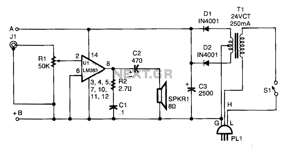
Line-operated-amplifier
T1 isolates the unit from the line and has a 24-V, center-tapped secondary. The output of the transformer is rectified by diodes D1 and D2 and filtered by capacitor C3 to provide 15 to 18 Vdc. The LM383 has built-in...

2W RF Amplifier with MOSFET LF2810A circuit diagram
Figure A illustrates the schematic of a microstrip single-stage RF amplifier. This amplifier utilizes the M/A-Com LF2810A MOSFET, which is rated for 10 watts and operates at 28 volts, but it delivers sufficient gain for this application at a supply...

100W Transmitter RF Power Amplifier 2SC2782
This is a 6-meter band transmitter RF power amplifier designed for 50 MHz operation, delivering an output power of 100 watts. It is intended for use with the FT-736R transceiver and is driven by a 10-watt signal for 6-meter SSB...

20w rf fm amplifier circuit
This FM RF amplifier utilizes two transistors from Philips: the BLV 10 and the BLW 87. The two RF transistors are configured in a chic C arrangement, providing an overall gain of 21 dB (100 times) with an efficiency of...
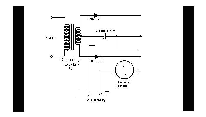
DIY Circuit Car Battery Charger
This simple circuit consists of a transformer, two diodes, a capacitor, and an ammeter. To charge a battery, connect the positive and negative terminals of the circuit to the corresponding terminals of the battery. When the battery is not charged,...
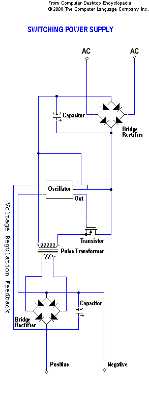
transformer circuit
A static device that couples two circuits to transfer alternating current (AC) from one circuit to another through electromagnetic induction. The current maintains the same frequency but may vary in voltage, phase, or impedance values. A transformer consists of two...

transformer Low voltage oscillator for joule thief
A transformer with two input leads and three output leads was used. An LED was connected to two of the output leads, and when a dead AA battery was connected to the input leads, the LED blinked for a brief...