


AC load impedance R3 added after
#feedback amplifier
#AC load
#impedance
#capacitor
#signal diversion
#bass
#frequency response
#audio amplifier
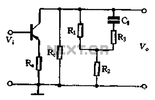
Description: The CL capacitor feedback amplifier exhibits an output signal diversion effect. In the bass range, the effect is not the same as that of an open diversion. As the frequency increases, the effect of CL becomes more pronounced, potentially leading to a short circuit with RT. Consequently, the input resistance of the tone circuitry is reduced from Ri + Rz to R20, which is typically greater than R2-foot-1 times or even 1-o-fold. This results in the amplifier experiencing negative effects when the bass and treble load carriers fall significantly short, causing a decrease in amplifier gain with rising frequency. Notably, in the treble range, there is a reduction in treble gain, which is counterbalanced by an increase in offset.
The CL capacitor feedback amplifier is designed to manipulate the output signal by utilizing a capacitor (CL) in the feedback loop. This configuration allows for selective frequency response adjustments, particularly in the bass and treble ranges. The behavior of the amplifier is influenced by the interaction between the capacitor and the resistive elements (Ri, Rz, and R20) in the circuit.
At lower frequencies, the feedback provided by the capacitor does not divert the signal as effectively as it does at higher frequencies. This results in a more linear response in the bass region, where the output signal is less affected by the feedback loop. However, as frequency increases, the capacitive reactance decreases, leading to an increased diversion effect. This can result in a situation where RT, the load resistance, effectively becomes short-circuited by the capacitor, causing a significant drop in the input resistance of the tone circuitry.
The input resistance transition from Ri + Rz to R20 indicates a change in the overall impedance seen by the amplifier. The specification that R20 is generally greater than R2-foot-1 times or even 1-o-fold suggests that the circuit is designed to maintain a certain level of stability and gain across a wide range of frequencies. However, when the load on the amplifier, particularly in the bass and treble ranges, becomes inadequate, the amplifier's gain begins to decrease. This is an important consideration in audio applications, as it can lead to an undesirable loss of fidelity in the output signal.
In the treble range, the amplifier experiences a reduction in gain, which is a common characteristic of many audio amplifiers. This reduction may be offset by other design elements within the circuit, aimed at enhancing overall performance. Careful consideration of component values and configurations is essential to achieve the desired balance between bass and treble response, ensuring that the amplifier operates effectively across the intended frequency spectrum. Cl capacitor feedback amplifier output signal diversion effect. In the bass, ct t is not similar to the open diversion effect. As the frequency increases, the streaming effect cl increases, and even the cl will Rt short circuit. Thus, the input resistance tone circuitry will be reduced by the Ri + Rz to R20 is usually greater than R2-foot-1 times or even 1-o-fold, so that the amplifier is negative when the bass and treble when the load carrier falls far short of that the amplifier gain decreases with increasing frequency. Obviously, in the treble, treble gain reduction and promotion of offsetting.
The CL capacitor feedback amplifier is designed to manipulate the output signal by utilizing a capacitor (CL) in the feedback loop. This configuration allows for selective frequency response adjustments, particularly in the bass and treble ranges. The behavior of the amplifier is influenced by the interaction between the capacitor and the resistive elements (Ri, Rz, and R20) in the circuit.
At lower frequencies, the feedback provided by the capacitor does not divert the signal as effectively as it does at higher frequencies. This results in a more linear response in the bass region, where the output signal is less affected by the feedback loop. However, as frequency increases, the capacitive reactance decreases, leading to an increased diversion effect. This can result in a situation where RT, the load resistance, effectively becomes short-circuited by the capacitor, causing a significant drop in the input resistance of the tone circuitry.
The input resistance transition from Ri + Rz to R20 indicates a change in the overall impedance seen by the amplifier. The specification that R20 is generally greater than R2-foot-1 times or even 1-o-fold suggests that the circuit is designed to maintain a certain level of stability and gain across a wide range of frequencies. However, when the load on the amplifier, particularly in the bass and treble ranges, becomes inadequate, the amplifier's gain begins to decrease. This is an important consideration in audio applications, as it can lead to an undesirable loss of fidelity in the output signal.
In the treble range, the amplifier experiences a reduction in gain, which is a common characteristic of many audio amplifiers. This reduction may be offset by other design elements within the circuit, aimed at enhancing overall performance. Careful consideration of component values and configurations is essential to achieve the desired balance between bass and treble response, ensuring that the amplifier operates effectively across the intended frequency spectrum. Cl capacitor feedback amplifier output signal diversion effect. In the bass, ct t is not similar to the open diversion effect. As the frequency increases, the streaming effect cl increases, and even the cl will Rt short circuit. Thus, the input resistance tone circuitry will be reduced by the Ri + Rz to R20 is usually greater than R2-foot-1 times or even 1-o-fold, so that the amplifier is negative when the bass and treble when the load carrier falls far short of that the amplifier gain decreases with increasing frequency. Obviously, in the treble, treble gain reduction and promotion of offsetting.

90-130W Audio Amplifier using 2N3773
Audio Amplifier with output power of either 100W or 130W. The output configuration can accommodate 2 transistors for 90W output or 4 transistors for 130W output. The PCB layout utilizes T3 on the heatsink. The component reference and values are...

22 Watt Audio Amplifier
The 22 watt amp is easy to build, and very inexpensive. The circuit can be used as a booster in a car audio system, an amp for satellite speakers in a surround sound or home theater system, or as an...

Power audio amplifier schematics with Tda2005
The TDA2005 integrated circuit (IC) features a high output power of 10W per channel (stereo) at a load of 2 ohms with a distortion of 10%, and 20W in bridge mode at a load of 4 ohms with a distortion...

5 Watt audio amplifier
The amplifier of circuit uses negative current feedback. The load current depends mainly on the input signal and not so much on the impedance of the loudspeaker. The inductor current of the loudspeaker develops a voltage across R7. This voltage...

AN12979A Audio Power Amplifier
The AN41240A is a single-chip integrated circuit (IC) designed for audio applications. It employs a single-hall-sensor drive on the input side of the spindle motor drive block and utilizes a low-noise direct PWM drive of sine wave on the output...

8 Watts Audio Amplifier (TDA2003)
Nice small audio amplifier which use only few parts to give good quality sound. This amp can be used as a simple booster, the heart of a more complicated amplifier or used as a guitar amp. Although not perfect, this...

60 watt audio amplifier
Using the STK4038X audio amplifier IC, can be designed a very simple high power and efficiency audio power amplifier. This circuit is manufactured by Sanyo Corporation and will provide an output power of 60 watts on an 8 ohms load...

Phase Control Circuit
A phase control circuit can be utilized to regulate the power supplied to an AC load. This circuit modulates the AC waveform by cutting portions of the cycle.
A phase control circuit is an essential component in various applications where the...

Fundamentals of Electrical Engineering and Class B audio amplifier
It is advisable to obtain TIP41 and TIP42 transistors, which are closely matched NPN and PNP power transistors with dissipation ratings of 65 watts each. If a TIP41 NPN transistor is unavailable, the TIP3055 (available from Radio Shack) serves as...