


Analog video switch and amplifier with direct coupled output
#analog switch
#CA3256
#direct-coupled output
#amplifier gain
#digital control
#video amplifier
#channel selection
#external resistor

Description: This circuit illustrates a CA3256 switch/amplifier configured for a direct-coupled output. One of four channels can be selected in parallel with channel 5. The analog switches of channels 1 to 4 are digitally controlled by logic. A VEE of -5 V is required, while Vcc can range from +5 to +12 V. The amplifier gain is determined by the external resistor Rf, as indicated by the equation.
The CA3256 circuit is designed to provide flexible switching and amplification capabilities across multiple channels. It features a direct-coupled output, which enhances the fidelity and speed of signal transmission, making it suitable for applications where minimal signal distortion is critical. The ability to select one of four channels in parallel with channel 5 allows for versatile signal routing, accommodating various configurations depending on the application requirements.
The digital control of the analog switches for channels 1 to 4 is implemented using a logic circuit, enabling precise selection and operation of the desired channel without the need for mechanical switches. This digital approach enhances reliability and reduces wear over time, which is particularly beneficial in applications requiring frequent channel switching.
Power supply requirements for this circuit stipulate a negative voltage (VEE) of -5 V, which is essential for proper operation of the CA3256 device. The positive supply voltage (Vcc) can be adjusted between +5 V and +12 V, allowing for compatibility with a range of systems and ensuring that the amplifier can operate efficiently within its specified limits.
The gain of the amplifier is adjustable through the use of an external feedback resistor (Rf). The relationship between the feedback resistor and the gain can be described by the appropriate gain equation, which should be referenced for accurate calculations. This feature provides flexibility in signal amplification, enabling the circuit to be tailored for specific signal levels as required by the application.
Overall, this circuit design offers a robust solution for applications requiring channel switching and amplification, with the added benefits of digital control and adjustable gain.This circuit shows a CA3256 switch/amplifier connected for a direct-coupled output. One of four channels can be selected in parallel with channel 5. The analog switches of channels 1 to 4 are digitally controlled by logic (Fig. 3-35B). A VEE of -5 V is required. Vcc can be from +5 to +12 V. Amplifier gain is determined by the external resistor Rf, as shown by the equaeion.
The CA3256 circuit is designed to provide flexible switching and amplification capabilities across multiple channels. It features a direct-coupled output, which enhances the fidelity and speed of signal transmission, making it suitable for applications where minimal signal distortion is critical. The ability to select one of four channels in parallel with channel 5 allows for versatile signal routing, accommodating various configurations depending on the application requirements.
The digital control of the analog switches for channels 1 to 4 is implemented using a logic circuit, enabling precise selection and operation of the desired channel without the need for mechanical switches. This digital approach enhances reliability and reduces wear over time, which is particularly beneficial in applications requiring frequent channel switching.
Power supply requirements for this circuit stipulate a negative voltage (VEE) of -5 V, which is essential for proper operation of the CA3256 device. The positive supply voltage (Vcc) can be adjusted between +5 V and +12 V, allowing for compatibility with a range of systems and ensuring that the amplifier can operate efficiently within its specified limits.
The gain of the amplifier is adjustable through the use of an external feedback resistor (Rf). The relationship between the feedback resistor and the gain can be described by the appropriate gain equation, which should be referenced for accurate calculations. This feature provides flexibility in signal amplification, enabling the circuit to be tailored for specific signal levels as required by the application.
Overall, this circuit design offers a robust solution for applications requiring channel switching and amplification, with the added benefits of digital control and adjustable gain.This circuit shows a CA3256 switch/amplifier connected for a direct-coupled output. One of four channels can be selected in parallel with channel 5. The analog switches of channels 1 to 4 are digitally controlled by logic (Fig. 3-35B). A VEE of -5 V is required. Vcc can be from +5 to +12 V. Amplifier gain is determined by the external resistor Rf, as shown by the equaeion.

Video amplifier provides digital gain control
The amplifier in Figure 1 originally served as the photomultiplier preamplifier in a Doppler system intended for eventual operation in the Martian atmosphere. The design is based on a switchable array of six Maxim MAX4258 dual-channel video multiplexer-amplifiers, IC1 through...

TV_video_processor
The EGG 1134 is a TV video processor that includes a picture intermediate frequency (IF) amplifier, a video detector, a video amplifier, keyed automatic gain control (AGC) with noise immunity, delayed AGC for the tuner, an automatic frequency tuning (AFT)...

Analog switches carrier suppression amplitude modulation circuit
An analog switch (double loop, double-break) and a differential modulation amplifier are used in this circuit. The carrier control switch operates by switching contacts at specific times, inverting the input modulation wave. When the next carrier signal is applied to...

High frequency analog switch
The commutator circuit delivers low impedance gate drive to the PN4091 analog switch for both on and off drive conditions. This circuit also achieves near-ideal gate drive conditions for high-frequency signal handling by offering low AC impedance during off drive...

video distibution amplifier with five
The circuit presented here has numerous applications. Essentially, the distribution amplifier receives a composite video signal from a video player (VCR) or a video generator (analog output) and buffers it, allowing it to be simultaneously sent to up to five...

LM1279 110 MHz RGB Video Amplifier System With OSD [Obsolete]
The LM231 and LM331 family of voltage-to-frequency converters are well-suited for use in simple, low-cost circuits designed for analog-to-digital conversion, precision frequency-to-voltage conversion, long-term integration, linear frequency modulation or demodulation, and various other applications. When utilized as a voltage-to-frequency converter,...

NJM2574 NJM2574 LOW VOLTAGE VIDEO AMPLIFIER WITH LPF
The NJM2670 is a general-purpose 60V dual H-bridge drive integrated circuit (IC). It features a pair of H-bridges, a thermal shutdown circuit, and an alarm output. The alarm output is capable of detecting application issues, thereby significantly enhancing system reliability...
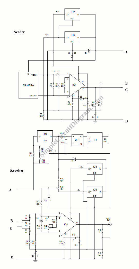
Long Distance Video Wire
This circuit is designed to connect a camera using a very long wire. It functions as a video amplifier. The circuit consists of two parts: the sender part and...
This circuit serves as a solution for transmitting video signals over extended...

Video cable driven by the MAX4104 4105 4304 4305 s an enlarged schematic
The circuit illustrated in the figure features a MAX4104/4105/4304/4305 video cable driver amplifier. This circuit is designed for use with coaxial transmission lines, optimizing the amplification of video signals to minimize reflections and maximize power transfer. The output impedance of...