


By the actual application circuit composed of a color picture tube with TDA6103Q
#TDA6103Q
#color picture tube
#R-G-B input
#signal amplifier
#video amplifier
#CRT
#resistor network
#input socket
#video signal
#display

Description: The circuit depicted in the figure integrates the TDA6103Q with a color picture tube, illustrating its practical application. The red, green, and blue (R, G, B) input signals are received from the input socket X3 and processed through a network of input resistors and capacitors before being fed into the TDA6103Q at pins 1, 2, and 3, respectively. The amplified output signals are then transmitted from pins 9, 8, and 7 through resistors R21, R22, and R23 to the three cathodes of the color picture tube: KR, KG, and KB. The emission of electrons from these cathodes generates the displayed images. The TDA6103Q is powered by a supply voltage connected to pin 1 of socket X1, providing +185V input voltage to pin 6 of the TDA6103Q. The circuit includes a network of potentiometers (R13, R6, R15, R4, R14) for white balance adjustment. Additionally, the cathodes of the color picture tube and the gate are designed with protective measures against gap discharge, ensuring that the output from the amplifier does not cause internal breakdown of the TDA6103Q during high-pressure discharges between the electrodes.
The TDA6103Q is a versatile RGB amplifier designed for driving color picture tubes. In this configuration, the input signals are conditioned through a resistor-capacitor network to ensure proper signal levels and frequency response before amplification. The output stage of the TDA6103Q provides the necessary drive currents to the cathodes of the color picture tube, where the emitted electrons interact with the phosphor coating on the inside of the tube to produce visible images.
The use of resistors R21, R22, and R23 is critical for controlling the current flowing to each cathode, allowing for precise color balance and intensity adjustments. The potentiometers included in the circuit offer a means to fine-tune the white balance, ensuring that the colors displayed on the screen are accurate and consistent. The careful selection of these components is essential for achieving optimal performance and maintaining image quality.
The protection against high-voltage discharge is a crucial aspect of this design, as it safeguards the TDA6103Q from potential damage due to electrical breakdown. This protective feature is particularly important in applications where high voltages are present, as it enhances the reliability and longevity of the circuit.
Overall, this schematic showcases a well-engineered solution for driving a color picture tube, emphasizing the importance of component selection, signal processing, and protective measures in high-voltage electronic applications. As shown in FIG grounds TDA6103Q and color picture tube composed of the actual application. R, G, B input signal from the input socket X3, through the input resistor network co nsists of capacitors into the TDA6103Q 1,2,3 feet, respectively, from the amplified signal output pin 9,8,7, through R21, R22, R23 is added to the color picture tube three cathodes KR, KG, KB, cathode emission electrons produce images. TDA6103Q supply voltage is provided by socket X1 pin 1 + 185V input voltage applied to TDA6103Q 6 feet.
Enter the network potentiometer R13, R6, R15, R4, R14 for the white balance adjustment potentiometer. Color picture tube cathode and the gate using protected forms gap discharge, the output of the amplifier to protect TDA6103Q internal breakdown will not be generated when the high pressure discharge between the electrodes.
The TDA6103Q is a versatile RGB amplifier designed for driving color picture tubes. In this configuration, the input signals are conditioned through a resistor-capacitor network to ensure proper signal levels and frequency response before amplification. The output stage of the TDA6103Q provides the necessary drive currents to the cathodes of the color picture tube, where the emitted electrons interact with the phosphor coating on the inside of the tube to produce visible images.
The use of resistors R21, R22, and R23 is critical for controlling the current flowing to each cathode, allowing for precise color balance and intensity adjustments. The potentiometers included in the circuit offer a means to fine-tune the white balance, ensuring that the colors displayed on the screen are accurate and consistent. The careful selection of these components is essential for achieving optimal performance and maintaining image quality.
The protection against high-voltage discharge is a crucial aspect of this design, as it safeguards the TDA6103Q from potential damage due to electrical breakdown. This protective feature is particularly important in applications where high voltages are present, as it enhances the reliability and longevity of the circuit.
Overall, this schematic showcases a well-engineered solution for driving a color picture tube, emphasizing the importance of component selection, signal processing, and protective measures in high-voltage electronic applications. As shown in FIG grounds TDA6103Q and color picture tube composed of the actual application. R, G, B input signal from the input socket X3, through the input resistor network co nsists of capacitors into the TDA6103Q 1,2,3 feet, respectively, from the amplified signal output pin 9,8,7, through R21, R22, R23 is added to the color picture tube three cathodes KR, KG, KB, cathode emission electrons produce images. TDA6103Q supply voltage is provided by socket X1 pin 1 + 185V input voltage applied to TDA6103Q 6 feet.
Enter the network potentiometer R13, R6, R15, R4, R14 for the white balance adjustment potentiometer. Color picture tube cathode and the gate using protected forms gap discharge, the output of the amplifier to protect TDA6103Q internal breakdown will not be generated when the high pressure discharge between the electrodes.

Video Signal Carrier Circuit
In the video system shown in Figs. A and R, a single coaxial cable transmits power to a remote location, selects one of eight video channels, and returns the chosen signal. This system can select from multiple remote surveillance camera...

Video-Out Coupling
To connect a video signal to multiple destinations, a distribution amplifier is required to match the 75-ohm video cable. This amplifier terminates the incoming cable at 75 ohms and provides several outputs, each maintaining a 75-ohm output impedance. Typically, this...

Video Preamp Circuit
An NE592 or LM733 is utilized as a general-purpose video amplifier in this schematic. J2 and J3 deliver two anti-phase outputs. R2 functions as a gain control. The bandwidth is approximately 100 MHz.
The NE592 and LM733 are integrated circuits designed...

Video amplifier 1
The objective is to enhance information transmission through the distribution of articles. For any issues related to article content, copyright, or other concerns, please reach out via email to [email protected] within 15 days. Prompt action will be taken to address...
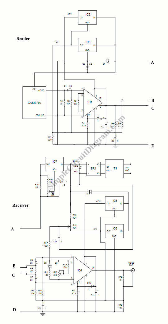
Long Distance Video Wire
This circuit is designed to connect a camera using a very long wire. It functions as a video amplifier. The circuit consists of two parts: the sender part and...
This circuit serves as a solution for transmitting video signals over extended...
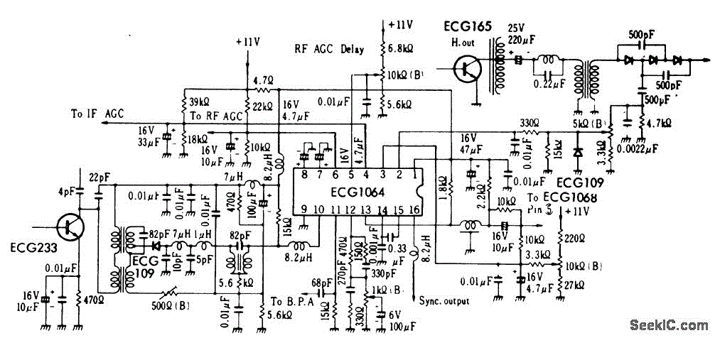
TV_video_signal_processor_circuit_1
TV video signal processor circuit. The ECG1064 chip includes a primary video amplifier, two sync pulse amplifiers, a look-out protector, a noise detector, two noise gates, an automatic gain control (AGC) detector, an intermediate frequency (IF) AGC amplifier, a base...

CRT final video driver amplifier
The CRT final video driver amplifier is a complementary push-pull final video driver amplifier composed of three transistors. VT511 functions as a driver amplifier, utilizing a common emitter configuration that offers high gain characteristics. The input signal from the polar...

TDA6103Q having a feedback factor of the test circuit
The TDA6103Q test circuit features a feedback factor of 1/150. Input signals Vi1, Vi2, and Vi3 are directed through an input resistor network that includes capacitors to the TDA6103Q pins 1, 2, and 3, which are part of the differential...

video on telephone line wires
The Videowire converts a baseband video signal into a low impedance differential signal that can be sent over ordinary four conductor telephone wire. A send board mounted close to the camera generates the differential signal and a receive board near...