


Class-A 100W Amplifier

Description: A Class A Class AB amplifier rated 100 Watts when driving a 4 ohm loudspeaker. This circuit developed out of my 30+ years of JLH class-A based investigations.
The original simple 1969 JLH class-A design provided excellent first cycle accuracy through mid and high frequencies (dynamic clarity) because there were no stabilization components nor a series output choke, whilst the NFB error correction was established via the input emitter (some describe this as current feedback). However, it did generate rather a lot of heat, the damping was soft at lower frequencies and the positive slew was weaker in the presence of loudspeaker system generated back-EMF at higher audio frequencies.
The Class A and Class AB amplifier circuit described operates at a power rating of 100 Watts into a 4-ohm load, making it suitable for driving high-performance loudspeakers. The design draws on the principles established in the original JLH class-A amplifier, which is known for its simplicity and high fidelity. The absence of stabilization components and output chokes contributes to the amplifier's ability to deliver dynamic audio with minimal distortion, particularly in the mid and high frequency ranges.
In this design, the feedback mechanism employs current feedback through the input emitter, which enhances the amplifier's responsiveness to audio signals, thereby improving the overall sound quality. This configuration allows for a more direct interaction between the input signal and the output stage, resulting in improved transient response and clarity.
However, the inherent characteristics of Class A operation lead to significant heat generation, necessitating adequate thermal management solutions such as heat sinks or active cooling systems. The soft damping effect observed at lower frequencies can be mitigated through careful selection of the output stage components, allowing for improved control over the loudspeaker's movement, which is crucial for achieving tight bass response.
In higher frequency ranges, the issue of back-EMF generated by the loudspeaker can introduce challenges in maintaining positive slew rates. To address this, the circuit may incorporate additional measures, such as improved feedback paths or compensatory circuitry, to enhance the amplifier's performance under dynamic load conditions.
Overall, this amplifier design exemplifies a balance between classic audio engineering principles and modern enhancements, aiming to deliver high-quality audio reproduction while addressing the thermal and dynamic challenges associated with high-power amplification.A Class A // Class AB amplifier rated 100 Watts when driving a 4 ohm loudspeaker. This circuit developed out of my 30+ years of JLH class-A based investigations. The original `simple` 1969 JLH class-A design provided excellent first cycle accuracy through mid and high frequencies (dynamic clarity) because there were no stabilisation components nor a series output choke, whilst the NFB error correction was established via the input emitter (some describe this as current feedback). However it did generate rather a lot of heat, the damping was `soft` at lower frequencies and the positive slew was weaker in the presence of loudspeaker system generated back-EMF at higher audio frequencies. I was eventually able to improve upo
The original simple 1969 JLH class-A design provided excellent first cycle accuracy through mid and high frequencies (dynamic clarity) because there were no stabilization components nor a series output choke, whilst the NFB error correction was established via the input emitter (some describe this as current feedback). However, it did generate rather a lot of heat, the damping was soft at lower frequencies and the positive slew was weaker in the presence of loudspeaker system generated back-EMF at higher audio frequencies.
The Class A and Class AB amplifier circuit described operates at a power rating of 100 Watts into a 4-ohm load, making it suitable for driving high-performance loudspeakers. The design draws on the principles established in the original JLH class-A amplifier, which is known for its simplicity and high fidelity. The absence of stabilization components and output chokes contributes to the amplifier's ability to deliver dynamic audio with minimal distortion, particularly in the mid and high frequency ranges.
In this design, the feedback mechanism employs current feedback through the input emitter, which enhances the amplifier's responsiveness to audio signals, thereby improving the overall sound quality. This configuration allows for a more direct interaction between the input signal and the output stage, resulting in improved transient response and clarity.
However, the inherent characteristics of Class A operation lead to significant heat generation, necessitating adequate thermal management solutions such as heat sinks or active cooling systems. The soft damping effect observed at lower frequencies can be mitigated through careful selection of the output stage components, allowing for improved control over the loudspeaker's movement, which is crucial for achieving tight bass response.
In higher frequency ranges, the issue of back-EMF generated by the loudspeaker can introduce challenges in maintaining positive slew rates. To address this, the circuit may incorporate additional measures, such as improved feedback paths or compensatory circuitry, to enhance the amplifier's performance under dynamic load conditions.
Overall, this amplifier design exemplifies a balance between classic audio engineering principles and modern enhancements, aiming to deliver high-quality audio reproduction while addressing the thermal and dynamic challenges associated with high-power amplification.A Class A // Class AB amplifier rated 100 Watts when driving a 4 ohm loudspeaker. This circuit developed out of my 30+ years of JLH class-A based investigations. The original `simple` 1969 JLH class-A design provided excellent first cycle accuracy through mid and high frequencies (dynamic clarity) because there were no stabilisation components nor a series output choke, whilst the NFB error correction was established via the input emitter (some describe this as current feedback). However it did generate rather a lot of heat, the damping was `soft` at lower frequencies and the positive slew was weaker in the presence of loudspeaker system generated back-EMF at higher audio frequencies. I was eventually able to improve upo

8W Amplifier Based on IC LM383
This circuit is an 8W audio amplifier utilizing the LM383 integrated circuit as its primary component. It is designed to be simple, cost-effective, and easy to assemble.
Component part list:
- C1: 10μF Electrolytic Capacitor
- C2: 470μF Electrolytic Capacitor
- C3: 0.1μF...

Audio amplifier with IC AN7522 AN7523 and TDA2616
The third series of the function utilizes the same system, specifically BTL (Bridge Transformer Less). This configuration offers several advantages, including the elimination of coupling capacitors and coupling transformers.
The BTL (Bridge Transformer Less) configuration is a significant advancement in audio...

36 watt audio power amplifier using tda1562q
It is based on a Philips class-H audio amplifier integrated circuit and can deliver 36W RMS or 70W music power, all from a 13.8V supply. The new Mighty Midget Amplifier can produce approximately 36W RMS continuously into a 4-ohm load...

10W Audio Amplifier With Bass-Boost
This design is based on an 18 Watt audio amplifier and was developed primarily to meet the needs of users who are unable to find the TLE2141C chip. It utilizes the widely available NE5532 dual integrated circuit; however, its power...

Audio Amplifer Circuit 230W With MOSFET IRFP2409240
This is a simple LED-powered audio amplifier circuit utilizing a MOSFET amplifier with the TL071C operational amplifier. It can deliver up to 45 W into an 8-ohm load. The circuit incorporates the MOSFETs IRFP240 and IRFP9240, which are recommended for...

stereo power amplifier 4w 8w with tda2005
This circuit is a class AB stereo audio power amplifier designed by Quasar for high-fidelity applications using a TDA2005 module. It is straightforward to construct and requires a minimal number of external components. The module includes output current protection and...
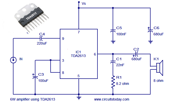
Audio power amplifier circuit using Hi Fi audio amplifier IC TDA2613
A simple and easy-to-build Hi-Fi audio power amplifier circuit is presented here. This 6-watt Hi-Fi audio amplifier circuit utilizes the TDA2613 integrated circuit (IC).
The circuit design employs the TDA2613, which is a high-performance audio amplifier IC known for its efficiency...

TDA8920BTH 200 watts d class amplifier circuit diagram
This high-power Class D audio amplifier electronic project is designed using the TDA8920BTH audio power amplifier IC. This power amplifier IC offers very high efficiency with minimal dissipation, yielding significant output power. The typical output power is 200 watts (2...
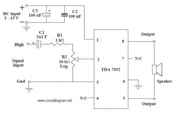
1W Mono Amplifier with TDA7052 circuit diagram
This is an audio amplifier circuit that uses the TDA7052 as the main component, along with five additional components to support its operation. The ideal supply voltage for this circuit is approximately 6-12V, and it does not require a heatsink.
The...