


Class AB Power Amplifier Circuit 30w Using Power Transistor
#class AB
#power amplifier
#30W
#power transistor
#variable resistor
#output offset
#quiescent current
#audio amplification
#circuit diagram

Description: A 30W Class AB power amplifier circuit diagram utilizes a power transistor. To set up the amplifier, adjust the variable resistor R1 to its maximum value and R12 to zero. After completing this setup, activate the amplifier. Adjust R1 until the measured output offset is between 30mV and 100mV. Once this is achieved, slowly adjust R12 to establish a quiescent current of approximately 120mA. It is important to continuously monitor the quiescent current as the amplifier heats up, as it may vary due to changes in voltage drops across the output devices caused by heat. The heatsinks should have a thermal resistance of 0.6K/W or lower for two amplifiers.
The 30W Class AB power amplifier is designed to provide high fidelity audio amplification with good efficiency. The circuit primarily consists of power transistors, which operate in a linear region to minimize distortion during audio signal amplification. The variable resistors R1 and R12 play crucial roles in setting the output offset voltage and quiescent current, respectively.
R1 is adjusted to control the output offset voltage, ensuring that the amplifier operates within the specified range of 30mV to 100mV. This adjustment is critical as it allows for proper biasing of the output stage, which is essential for linear operation and to prevent crossover distortion.
R12 is used to set the quiescent current, which is the idle current flowing through the output transistors when no input signal is present. A quiescent current of around 120mA is recommended to balance performance and thermal stability. As the amplifier operates, it generates heat, which can affect the quiescent current. Therefore, continuous monitoring is necessary to maintain optimal performance.
The thermal management of the amplifier is also vital. Heatsinks with a thermal resistance of 0.6K/W or lower are recommended for two amplifiers to ensure that the transistors remain within their safe operating temperatures. This is crucial for maintaining reliability and longevity in the amplifier's performance. Proper heatsinking will dissipate the heat generated during operation, preventing thermal runaway conditions that could lead to failure of the output devices.
Overall, careful setup and adjustment of the variable resistors, along with effective thermal management, are essential for the successful operation of the 30W Class AB power amplifier.30W Class AB power amplifier circuit diagram using power transistor. Set the above amplifier up by adjust the variable resistor R1 to maximum and R12 to zero. After this set up is done, the activate / turn on the amplifier. Adjust the R1 so that the measured output offset is between 30 and 100mV. Once set, adjust the R12 slowly to achieve a quiesc ent current of around 120mA. Keep checking the quiescent current as the amplifier heats up as it might change due to voltage drop changes in the output devices because of the heat. The heatsinks should be 0. 6K/W or less for two amplifiers.
The 30W Class AB power amplifier is designed to provide high fidelity audio amplification with good efficiency. The circuit primarily consists of power transistors, which operate in a linear region to minimize distortion during audio signal amplification. The variable resistors R1 and R12 play crucial roles in setting the output offset voltage and quiescent current, respectively.
R1 is adjusted to control the output offset voltage, ensuring that the amplifier operates within the specified range of 30mV to 100mV. This adjustment is critical as it allows for proper biasing of the output stage, which is essential for linear operation and to prevent crossover distortion.
R12 is used to set the quiescent current, which is the idle current flowing through the output transistors when no input signal is present. A quiescent current of around 120mA is recommended to balance performance and thermal stability. As the amplifier operates, it generates heat, which can affect the quiescent current. Therefore, continuous monitoring is necessary to maintain optimal performance.
The thermal management of the amplifier is also vital. Heatsinks with a thermal resistance of 0.6K/W or lower are recommended for two amplifiers to ensure that the transistors remain within their safe operating temperatures. This is crucial for maintaining reliability and longevity in the amplifier's performance. Proper heatsinking will dissipate the heat generated during operation, preventing thermal runaway conditions that could lead to failure of the output devices.
Overall, careful setup and adjustment of the variable resistors, along with effective thermal management, are essential for the successful operation of the 30W Class AB power amplifier.30W Class AB power amplifier circuit diagram using power transistor. Set the above amplifier up by adjust the variable resistor R1 to maximum and R12 to zero. After this set up is done, the activate / turn on the amplifier. Adjust the R1 so that the measured output offset is between 30 and 100mV. Once set, adjust the R12 slowly to achieve a quiesc ent current of around 120mA. Keep checking the quiescent current as the amplifier heats up as it might change due to voltage drop changes in the output devices because of the heat. The heatsinks should be 0. 6K/W or less for two amplifiers.

amplifier 1
A power amplifier is an amplifier designed to deliver maximum power output to a load. For example, in an audio system, it is the component responsible for driving speakers.
A power amplifier is a critical component in various electronic systems, particularly...
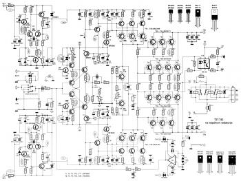
Power Amplifier 2000 Watt
This is a linear amplifier that requires advanced knowledge in electronics due to the complexity of the schematic diagram for a handmade circuit. It is advisable to redesign the schematic diagram using circuit design software such as DipTrace, Eagle, or...

60W power amplifier
The TDA7294 amplifier module is a monolithic integrated circuit designed for use as an audio class AB amplifier in hi-fi applications. It has a wide voltage range and output current capability, enabling it to supply the highest power into both...

300BSE power amplifier circuit
A request for a DIY 300BSE power amplifier schematic is made, with a specification to utilize Lowther PM6 speakers.
The 300BSE power amplifier is a well-regarded audio amplification circuit known for its warm sound and high fidelity, particularly suited for driving...
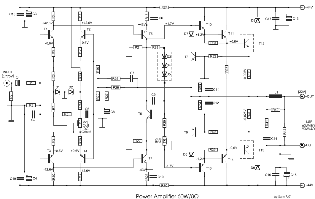
power amplifier 60w8
This circuit was designed and manufactured in the 1980s. Since then, it has operated without issues. There are no significant constructional challenges, aside from the usual considerations: ensuring the appropriate power supply voltage, selecting a suitable heatsink, and properly matching...

60 watt 2n3055 power amplifier
This architecture allows for a wide tolerance in component selection, enabling the use of various components that may be readily available. The transistors utilized can be any NPN type power transistor, excluding Darlington configurations. The output power is approximately 60W....

60 Watt Into 8 Ohms Power Amplifier
Cleaned Input: This amplifier does not claim to be state of the art, and in fact the base design is now over 20 years old. It is a simple amp to build, uses commonly available parts and is stable and...

Power Amplifier OCL 50W by Mosfet (K1058 + J162)
The 50W Power Amplifier OCL Mosfet (K1058 + J162) is simple to construct and cost-effective. It requires a power supply of +35V and -35V at 2A. The Power Mosfet used in this design is K1058 and J162.
The 50W OCL (Output...

20W 40-500kHz PA 01
A 20W power amplifier circuit is illustrated in Figure 8-3. It features a pre-release level and enhances the power level through three stages to minimize significant phase shifts in the feedback loop. PNP silicon transistors are selected for both the...