


Class-d-power-amplifier
#class-d
#power amplifier
#pulse-width modulation
#audio
#op-amp
#comparator
#triangular wave
#square wave
#2-MHz clock

Description: In this circuit, a 2-MHz clock is divided by eight in U1, resulting in a stable 250-kHz carrier. Q1 and Q2 buffer the clock, providing a low-impedance drive for operational amplifier U4, which functions as a high-gain amplifier and integrator. U4 accepts audio inputs and transforms the 250-kHz square wave into a triangular wave. The combined audio and triangular-wave signal is fed into comparator U7, where it is compared with a defined reference to generate a pulse-width modulated signal at the output of U7. The output devices operate between the +50 V and -50 V power rails in a complementary manner, driving an output filter that is a sixth-order Butterworth low-pass type, which demodulates the audio while attenuating the carrier and high-frequency components. Feedback is provided by resistor R1, and the amplifier gain is determined by the ratio of R1 to R2. Specifications include 200 W continuous power into a 4-ohm load, a frequency response of 20 to 20 kHz with +0.5, -1.0 dB at 200 W, total harmonic distortion (THD) of less than 0.5% at 200 W, a 1.5-V rms input for rated output, a 69 dB signal-to-noise ratio with A-weighting, and a slew rate of 6.6 V/ms.
The circuit operates as a high-efficiency audio amplifier utilizing pulse-width modulation (PWM) for signal processing. The initial clock signal generated at 2 MHz is effectively divided down to 250 kHz to serve as the carrier frequency. The use of Q1 and Q2 as buffer stages ensures that the clock signal is delivered with low impedance, which is critical for maintaining signal integrity when interfacing with U4. The operational amplifier U4 plays a pivotal role in shaping the audio signal; by integrating the square wave from the clock into a triangular waveform, it prepares the signal for further modulation.
Comparator U7 is essential for PWM generation, where it compares the processed audio signal against a reference voltage. This comparison results in a modulated output that varies in width according to the amplitude of the audio input, allowing for efficient amplification while minimizing power losses. The output stage employs complementary switching devices, which alternate between the positive and negative supply rails, thus enhancing efficiency and reducing heat generation.
The sixth-order Butterworth low-pass filter is designed to effectively demodulate the PWM signal, ensuring that the audio output is clean and free from high-frequency artifacts associated with the modulation process. The feedback mechanism through R1 is critical for maintaining stability and ensuring the desired gain of the amplifier, which is determined by the ratio of R1 to R2. This configuration allows for precise control over the amplifier's response characteristics.
With a continuous power output of 200 W into a 4-ohm load, the amplifier is capable of delivering high-quality audio across the specified frequency range. The performance metrics, including low total harmonic distortion and a favorable signal-to-noise ratio, indicate that the circuit is well-suited for high-fidelity audio applications. The specified slew rate further supports the amplifier's ability to handle rapid changes in signal amplitude, making it appropriate for dynamic audio sources. Overall, this circuit exemplifies an effective design for a high-power audio amplifier utilizing advanced modulation techniques.In this circuit, a 2-MHz clock is divided by eight in Ul, providing a stable 250-kHz carrier. Ql and Q2 buffer the clock and provide a low-impedance drive for op amp U4, which is a high-gain amplifier and integrator. U4 accepts audio inputs and converts the 250-kHz square wave into a triangular wave. The summed audio and triangular-wave signal is applied to the input of comparator U7, where it is compared with a de reference to produce a pulse-width modulated signal at the output of U7.
The output devices switch between the +50 V and -50 V rails in a complementary fashion, driving the output filter that is a sixth-order Butterworth low-pass type, which demodulates the audio and attenuates the carrier and higli frequency components. Feedback is provided R1; amplifier gain is R1R,. Specifications: 200 W continuous power into a 4-flload; 20 to 20kHz frequency response +0.5, -1.0 dB at 200 W; THD, !MD (";; 0.5% at 200 W; 1.5-V rms input for rated output; 69 dB SIN ratio, A weighting; 6.6-V ms slew rate.
The circuit operates as a high-efficiency audio amplifier utilizing pulse-width modulation (PWM) for signal processing. The initial clock signal generated at 2 MHz is effectively divided down to 250 kHz to serve as the carrier frequency. The use of Q1 and Q2 as buffer stages ensures that the clock signal is delivered with low impedance, which is critical for maintaining signal integrity when interfacing with U4. The operational amplifier U4 plays a pivotal role in shaping the audio signal; by integrating the square wave from the clock into a triangular waveform, it prepares the signal for further modulation.
Comparator U7 is essential for PWM generation, where it compares the processed audio signal against a reference voltage. This comparison results in a modulated output that varies in width according to the amplitude of the audio input, allowing for efficient amplification while minimizing power losses. The output stage employs complementary switching devices, which alternate between the positive and negative supply rails, thus enhancing efficiency and reducing heat generation.
The sixth-order Butterworth low-pass filter is designed to effectively demodulate the PWM signal, ensuring that the audio output is clean and free from high-frequency artifacts associated with the modulation process. The feedback mechanism through R1 is critical for maintaining stability and ensuring the desired gain of the amplifier, which is determined by the ratio of R1 to R2. This configuration allows for precise control over the amplifier's response characteristics.
With a continuous power output of 200 W into a 4-ohm load, the amplifier is capable of delivering high-quality audio across the specified frequency range. The performance metrics, including low total harmonic distortion and a favorable signal-to-noise ratio, indicate that the circuit is well-suited for high-fidelity audio applications. The specified slew rate further supports the amplifier's ability to handle rapid changes in signal amplitude, making it appropriate for dynamic audio sources. Overall, this circuit exemplifies an effective design for a high-power audio amplifier utilizing advanced modulation techniques.In this circuit, a 2-MHz clock is divided by eight in Ul, providing a stable 250-kHz carrier. Ql and Q2 buffer the clock and provide a low-impedance drive for op amp U4, which is a high-gain amplifier and integrator. U4 accepts audio inputs and converts the 250-kHz square wave into a triangular wave. The summed audio and triangular-wave signal is applied to the input of comparator U7, where it is compared with a de reference to produce a pulse-width modulated signal at the output of U7.
The output devices switch between the +50 V and -50 V rails in a complementary fashion, driving the output filter that is a sixth-order Butterworth low-pass type, which demodulates the audio and attenuates the carrier and higli frequency components. Feedback is provided R1; amplifier gain is R1R,. Specifications: 200 W continuous power into a 4-flload; 20 to 20kHz frequency response +0.5, -1.0 dB at 200 W; THD, !MD (";; 0.5% at 200 W; 1.5-V rms input for rated output; 69 dB SIN ratio, A weighting; 6.6-V ms slew rate.
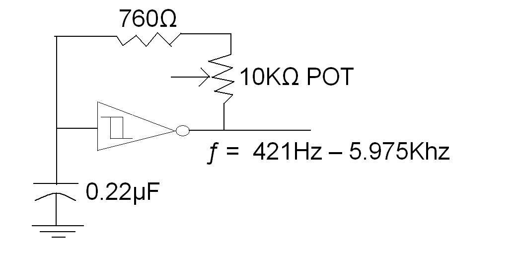
square wave 2 sine wave convertion
A TTL square wave needs to be converted into a sine wave, with a frequency range of 4Hz to 60Hz. One method to achieve this is by filtering the square wave using a high-order filter. However, if the frequency varies,...

Square Wave Generator
One unit is in good condition, manufactured in 1979, and is capable of generating sine, triangle, and square waveforms. This unit is retained and utilized as the primary function generator for testing purposes at the main office location. The other...
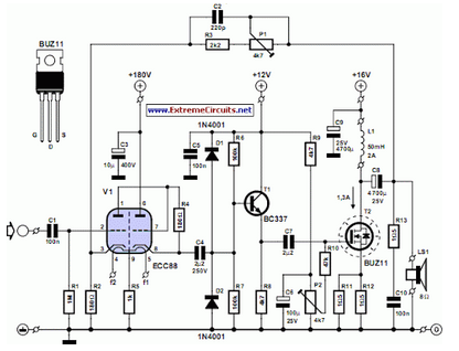
Simple Hybrid Audio Amplifier
The debate continues regarding whether valves or transistors are superior. This discussion will not be addressed here. However, if one cannot make their…
The comparison between valves (vacuum tubes) and transistors has been a longstanding topic in the field of electronics,...

Window comparator
This circuit produces an output of 0V when the input voltage is within a specified range defined by two reference voltages. When the input voltage falls outside this range, the output becomes positive. Two operational amplifiers (op-amps) function as voltage...

Simple Square Wave Generator with 7400
This is a simple square wave generator circuit constructed using the IC 74LS00, capable of producing square wave signals with frequencies ranging from 20 Hz to 1 MHz. The circuit exhibits sufficient stability for most applications. The output frequency is...

Super audio Reverb
Blue VALUES replaced by values in RED. Blue COMPONENTS removed from circuit. Red components added to circuit.
In this circuit modification, the original design underwent significant changes where blue values were substituted with corresponding red values to enhance performance or compatibility....

automatic loudness control circuit schematic
To achieve optimal audio reproduction at varying listening levels, it is essential to adjust tone control settings to align with the established characteristics of human auditory perception. The sensitivity of the human ear changes non-linearly across the entire audible frequency...
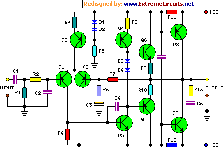
45 Watt Class-B Audio Power Amplifier
The goals were achieved by utilizing a discrete-component operational amplifier (op-amp) driving a bipolar junction transistor (BJT) complementary common-emitter output stage configured for Class B operation. In this configuration, the output transistors remain off for small output currents, allowing the...

op amp Op Amp based Colpitts oscillator
An op-amp based Colpitts oscillator in Multisim displays a "timestep too small" error when the run button is pressed. Despite extensive research and attempts to resolve the issue, the error persists. The design features a C-L-C pi circuit that is...