


Data-based Load Pull Amplifier
#ADS
#behavioral model
#harmonic balance simulation
#load pull
#RF amplifier
#1-tone
#fixed input power
#schematic
#System - Data Models
#circuit level

Description: The AmpLoadPull project demonstrates the utilization of the AmpLoadPull and LoadPullSetup components in Advanced Design System (ADS). These components are part of the ADS behavioral model suite located within the System - Data Models palette. The schematic "circuit_level_amplifier_1_tone.dsn" represents a circuit-level simulation for a 1-tone fixed input power swept reflection coefficient harmonic balance analysis of the amplifier. Additionally, "behavioral_level_amplifier_setup.dsn" is a schematic that employs LoadPullSetup to create the behavioral model for the amplifier, with results stored in the dataset "behavioral_level_amplifier_setup.ds." Furthermore, "behavioral_level_amplifier_1_tone.dsn" provides a schematic for a behavioral level 1-tone fixed input power swept reflection coefficient harmonic balance simulation of the amplifier using AmpLoadPull, with results stored in the dataset "behavioral_level_amplifier_1_tone.ds." Figure 1 presents a comparison of circuit and behavioral level results from a Harmonic Balance load pull analysis, specifically detailing the power delivered to the load and power added efficiency for both 50 Ohm and 10 Ohm reference impedances, showing generally good agreement.
The AmpLoadPull project is a comprehensive framework designed for analyzing amplifier performance using two primary methodologies: circuit-level and behavioral-level simulations. The project leverages the capabilities of ADS, which provides a robust environment for simulating RF and microwave circuits. The AmpLoadPull component is specifically engineered to facilitate load-pull analysis, allowing engineers to evaluate how varying load impedances affect amplifier performance metrics such as output power and efficiency.
The "circuit_level_amplifier_1_tone.dsn" schematic is crucial for performing a detailed circuit-level analysis. It incorporates a fixed input power level while sweeping the reflection coefficient to assess the amplifier's harmonic balance across a single tone. This simulation aims to provide insights into the amplifier's linearity and efficiency under defined input conditions.
In contrast, the "behavioral_level_amplifier_setup.dsn" schematic serves as a foundational setup for generating behavioral models. By utilizing LoadPullSetup, this schematic allows for the abstraction of complex amplifier behaviors into manageable models that can be easily manipulated and simulated. The results from this setup are essential for understanding the amplifier's performance in a more generalized context without the need for intricate circuit-level details.
The "behavioral_level_amplifier_1_tone.dsn" schematic further extends the analysis by employing the AmpLoadPull component to conduct a behavioral-level simulation. This approach enables the examination of how the amplifier behaves under varying conditions while maintaining a fixed input power level. The dataset "behavioral_level_amplifier_1_tone.ds" stores the results of this simulation, which can be compared against the circuit-level results to identify discrepancies and validate the accuracy of the behavioral model.
Figure 1 serves as a visual representation of the comparative analysis between circuit-level and behavioral-level results from the Harmonic Balance load pull analysis. It highlights critical performance metrics, specifically the power delivered to the load and power added efficiency, across different reference impedances (50 Ohm and 10 Ohm). The generally good agreement observed in the results underscores the reliability of both simulation methodologies in predicting amplifier performance. This comprehensive approach provides engineers with valuable insights into the design and optimization of amplifiers for various applications.The AmpLoadPull project illustrates the use of the AmpLoadPull and LoadPullSetup components in ADS. These components are part of the ADS behavioral model suite found under the System - Data Models palette. "circuit_level_amplifier_1_tone. dsn" is a schematic for a circuit level 1-tone fixed input power swept reflection coefficient harmonic balance simulation of the amplifier.
The result is in the dataset "circuit_level_amplifier_1_tone. ds. " "behavioral_level_amplifier_setup. dsn" is a schematic using LoadPullSetup for the generation of the behavioral model for the amplifier. The result is in the dataset "behavioral_level_amplifier_setup. ds. " "behavioral_level_amplifier_1_tone. dsn" is a schematic for a behavioral level 1-tone fixed input power swept reflection coefficient harmonic balance simulation of the amplifier of interest using AmpLoadPull along with the dataset "behavioral_level_amplifier_setup.
ds. " The result is in the dataset "behavioral_level_amplifier_1_tone. ds. " In Figure 1, a comparison of circuit and behavioral level results is given for a Harmonic Balance loadpull analysis. Specifically, results for power delivered to the load and power added efficiency are given for both a 50 Ohm and 10 Ohm reference impedance.
The agreement is generally good.
The AmpLoadPull project is a comprehensive framework designed for analyzing amplifier performance using two primary methodologies: circuit-level and behavioral-level simulations. The project leverages the capabilities of ADS, which provides a robust environment for simulating RF and microwave circuits. The AmpLoadPull component is specifically engineered to facilitate load-pull analysis, allowing engineers to evaluate how varying load impedances affect amplifier performance metrics such as output power and efficiency.
The "circuit_level_amplifier_1_tone.dsn" schematic is crucial for performing a detailed circuit-level analysis. It incorporates a fixed input power level while sweeping the reflection coefficient to assess the amplifier's harmonic balance across a single tone. This simulation aims to provide insights into the amplifier's linearity and efficiency under defined input conditions.
In contrast, the "behavioral_level_amplifier_setup.dsn" schematic serves as a foundational setup for generating behavioral models. By utilizing LoadPullSetup, this schematic allows for the abstraction of complex amplifier behaviors into manageable models that can be easily manipulated and simulated. The results from this setup are essential for understanding the amplifier's performance in a more generalized context without the need for intricate circuit-level details.
The "behavioral_level_amplifier_1_tone.dsn" schematic further extends the analysis by employing the AmpLoadPull component to conduct a behavioral-level simulation. This approach enables the examination of how the amplifier behaves under varying conditions while maintaining a fixed input power level. The dataset "behavioral_level_amplifier_1_tone.ds" stores the results of this simulation, which can be compared against the circuit-level results to identify discrepancies and validate the accuracy of the behavioral model.
Figure 1 serves as a visual representation of the comparative analysis between circuit-level and behavioral-level results from the Harmonic Balance load pull analysis. It highlights critical performance metrics, specifically the power delivered to the load and power added efficiency, across different reference impedances (50 Ohm and 10 Ohm). The generally good agreement observed in the results underscores the reliability of both simulation methodologies in predicting amplifier performance. This comprehensive approach provides engineers with valuable insights into the design and optimization of amplifiers for various applications.The AmpLoadPull project illustrates the use of the AmpLoadPull and LoadPullSetup components in ADS. These components are part of the ADS behavioral model suite found under the System - Data Models palette. "circuit_level_amplifier_1_tone. dsn" is a schematic for a circuit level 1-tone fixed input power swept reflection coefficient harmonic balance simulation of the amplifier.
The result is in the dataset "circuit_level_amplifier_1_tone. ds. " "behavioral_level_amplifier_setup. dsn" is a schematic using LoadPullSetup for the generation of the behavioral model for the amplifier. The result is in the dataset "behavioral_level_amplifier_setup. ds. " "behavioral_level_amplifier_1_tone. dsn" is a schematic for a behavioral level 1-tone fixed input power swept reflection coefficient harmonic balance simulation of the amplifier of interest using AmpLoadPull along with the dataset "behavioral_level_amplifier_setup.
ds. " The result is in the dataset "behavioral_level_amplifier_1_tone. ds. " In Figure 1, a comparison of circuit and behavioral level results is given for a Harmonic Balance loadpull analysis. Specifically, results for power delivered to the load and power added efficiency are given for both a 50 Ohm and 10 Ohm reference impedance.
The agreement is generally good.

10w 225-400mhz linear amplifier
This broadband amplifier operates within the 225-400 MHz military communications band, delivering an RF output power of 10 watts while powered by a 28-volt supply. It is suitable for use as a driver for higher power devices such as the...

250mw 16 db vhf amplifier
This project involves a 250mW RF power amplifier circuit. It is designed to amplify the output of approximately 7mW wideband FM transmitters to a final output level of about 250mW. The circuit utilizes a simple two-transistor VHF power amplifier configuration,...
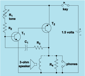
schematic diagram graphic arts
Schematic diagram. A presentation of the element-by-element relationship of all parts of a system.
A schematic diagram serves as a crucial tool in electronic design and engineering, representing the interconnections and relationships between various components within a system. It provides a...

WWV receiver circuit
The RF amplifier Q3 connects to diodes D1 to D4 within the mixer. Transistors Q1 and Q2, through transformers T1 and T2, facilitate the injection of liquid oxygen at 10 MHz for diodes D1, operational amplifier U1A, and U1B. Operational...

RF amplifier circuit 1W 2.3GHz MRF2001
RF amplifier circuit diagram, delivering 1W for 2.3GHz, built based on MRF2001. This RF amplifier provides approximately 1 Watt power output with a minimum gain of 8 dB at a 24V voltage supply. The frequency can be tuned from 2.25GHz...

70MHz RF FM Power Amplifier
This 70 MHz RF power amplifier circuit utilizes the SD1143 transistor, which offers a gain of approximately 14 dB in this configuration. The design leverages the characteristics of a 175 MHz device.
The RF power amplifier circuit designed around the SD1143...

20w rf fm amplifier circuit
This FM RF amplifier utilizes two transistors from Philips: the BLV 10 and the BLW 87. The two RF transistors are configured in a chic C arrangement, providing an overall gain of 21 dB (100 times) with an efficiency of...

100W RF Amplifier Circuit With BLY94 Transistor
This is a component of a 100W RF amplifier. This circuit is constructed using the RF power transistor BLY94. Components include the BLY94 transistor, inductor, and others.
The 100W RF amplifier circuit utilizing the BLY94 transistor is designed to amplify radio...

LOW NOISE 420 MHz ATV RECEIVER CONVERTER
L1, Q1, L2, and L3 form an RF amplifier stage that drives M1, a doubly balanced mixer. Q4 serves as a local oscillator stage operating in the 375-MHz range. Signals in the 420 to 450-MHz range from Q1 are mixed...