


First POWER MOSFET Amplifier by K134+J49

Description: This is the first MOSFET power amplifier designed, featuring a comprehensive circuit. As a 60-watt power amplifier, it is adequate for typical usage.
The 60-watt MOSFET power amplifier circuit is designed to deliver high efficiency and robust performance for audio amplification applications. The circuit typically consists of several key components, including MOSFET transistors, resistors, capacitors, and a power supply unit.
The heart of the amplifier is the MOSFET transistor, chosen for its high input impedance and low output capacitance, which contribute to improved linearity and reduced distortion. The circuit configuration often employs a complementary push-pull arrangement, utilizing both N-channel and P-channel MOSFETs to enhance performance across the audio frequency spectrum.
The input stage of the amplifier usually includes a differential amplifier configuration to ensure high gain and minimal noise. This stage may be followed by a voltage gain stage that drives the output stage. Feedback mechanisms are often implemented to stabilize the gain and improve linearity, reducing the total harmonic distortion (THD) of the amplifier.
Power supply considerations are crucial for the performance of the amplifier. A regulated power supply is recommended to maintain consistent voltage levels, which helps in minimizing fluctuations that could affect audio quality. Additionally, decoupling capacitors are placed close to the MOSFETs to filter out high-frequency noise and ensure stable operation.
Thermal management is also an important aspect of the design. Adequate heatsinking is required to dissipate heat generated by the MOSFETs during operation, preventing thermal runaway and ensuring reliable performance over extended periods.
Overall, this 60-watt MOSFET power amplifier circuit is suitable for various applications, including home audio systems, musical instrument amplifiers, and other audio-related projects, providing a balance of power, efficiency, and sound quality.This has been the first Mosfet power amplifier of me, It is the most complete circuit. As a 60 watt power amplifier, this is sufficient for normal use in my..
The 60-watt MOSFET power amplifier circuit is designed to deliver high efficiency and robust performance for audio amplification applications. The circuit typically consists of several key components, including MOSFET transistors, resistors, capacitors, and a power supply unit.
The heart of the amplifier is the MOSFET transistor, chosen for its high input impedance and low output capacitance, which contribute to improved linearity and reduced distortion. The circuit configuration often employs a complementary push-pull arrangement, utilizing both N-channel and P-channel MOSFETs to enhance performance across the audio frequency spectrum.
The input stage of the amplifier usually includes a differential amplifier configuration to ensure high gain and minimal noise. This stage may be followed by a voltage gain stage that drives the output stage. Feedback mechanisms are often implemented to stabilize the gain and improve linearity, reducing the total harmonic distortion (THD) of the amplifier.
Power supply considerations are crucial for the performance of the amplifier. A regulated power supply is recommended to maintain consistent voltage levels, which helps in minimizing fluctuations that could affect audio quality. Additionally, decoupling capacitors are placed close to the MOSFETs to filter out high-frequency noise and ensure stable operation.
Thermal management is also an important aspect of the design. Adequate heatsinking is required to dissipate heat generated by the MOSFETs during operation, preventing thermal runaway and ensuring reliable performance over extended periods.
Overall, this 60-watt MOSFET power amplifier circuit is suitable for various applications, including home audio systems, musical instrument amplifiers, and other audio-related projects, providing a balance of power, efficiency, and sound quality.This has been the first Mosfet power amplifier of me, It is the most complete circuit. As a 60 watt power amplifier, this is sufficient for normal use in my..

mosfet Reverse polarity protection
When a reverse voltage of 10V is applied to the source while the drain is grounded, the gate-source voltage (Vgs) becomes -10V. This voltage is significantly above the threshold, which allows the MOSFET to remain in the saturation region, enabling...

22w stereo amplifier
This document presents a 22-watt stereo audio power amplifier circuit diagram utilizing the TDA1554 integrated circuit from NXP Semiconductors (formerly Philips Semiconductors). The circuit is designed to effectively amplify stereo signals and is characterized by its simplicity and utility. It...

Transmitting Audio Streams in Automotive Applications Using the MAX9205/MAX9206 LVDS SerDes
This application note outlines the transmission of I²S audio data streams between two audio components using a single shielded twisted-pair (STP) wire, employing the MAX9205 10-bit LVDS serializer and the MAX9206 10-bit LVDS deserializer. Low-voltage differential signaling (LVDS) serves as...
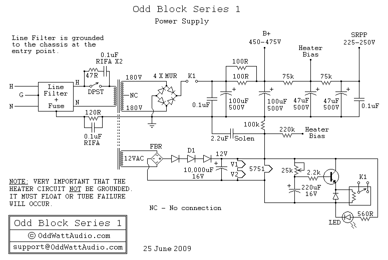
Audio Odd Block KT88 Series 1 Tube Amp-Power Supply
A schematic of the ability accumulation is presented below. Similar to the amplifier schematic, the ability accumulation design is © OddWatt Audio, and permission to host the schematic on this platform has been granted by OddWatt Audio. The schematic may...

DC Analysis of a MOSFET Transistor Circuit
During DC analysis, all AC voltage sources are removed from the circuit since they are AC sources. DC analysis focuses solely on DC sources. Additionally, all capacitors are removed because, in a DC context, capacitors act as open circuits. Consequently,...

MOSFET IRF510 Capacitor Discharge Ignition(CDI) Circuit and explanation
A 2 µF capacitor is charged to approximately 340 volts, and the discharge is controlled by a silicon-controlled rectifier (SCR). A Schmitt trigger oscillator (74C14) and a MOSFET (IRF510) are utilized to drive the low-voltage side of a small (120/12...

LM4561 LM4562 consisting of 170W power amplifier circuit
Figure (a) illustrates a 170W output amplifier circuit designed for a 4-ohm load. The LM4651 is a class D amplifier presented in a 28-pin DIP package, with its internal equivalent circuit depicted in Figure (c).
The 170W output amplifier circuit is...

mosfet How to switch between a solar panel and battery
A 12V battery is charged using a solar panel. When the battery reaches 12V, the solar panel is disconnected from the battery, and the load is connected to the battery. The solar panel is reconnected to the battery when the...

Compact 100W power amplifier circuit
The pLPC1342V and NE are two companies involved in a tube amplifier circuit utilizing 2SA1227A and 2SC2987A transistors, achieving a maximum output power of up to 120W with a cutoff frequency of up to 500 MHz. The circuit, illustrated in...