


guitar amplifier electronic 60 watt
#guitar amplifier
#60 watt
#single-rail supply
#capacitor-coupling
#audio amplifier
#high power output
#simple circuitry
#analog amplifier

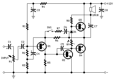
Description: This guitar amplifier electronic architecture utilizes a robust conventional circuit design for the power amplifier, employing a single-rail supply of approximately 60V and capacitor coupling for the speakers. The advantages of this configuration for a guitar amplifier include a straightforward circuit, even for relatively high power outputs, and a certain degree of loudspeaker protection due to capacitor C8, which prevents voltage buildup from reaching the loudspeakers in the event of a failure of the output transistors. The preamplifier is powered by the same 60V supply as the power amplifier, allowing for a two-transistor gain block capable of delivering around 20V RMS output. This setup provides a very high input impedance capability. The Darlington transistor types suggested may be too large for this design, and alternatives such as MJ11014 (Q3) and MJ11013 (Q4) or TIP142 (Q3) and TIP147 (Q4) can be utilized. D1 and D2 can be any Schottky-barrier diode types; however, using common 1N4148 silicon diodes for D1 and D2 will yield a softer harmonic modulation operation. In all instances where Darlington transistors are employed as output devices, it is crucial that the sensing transistor (Q2) is in close thermal contact with the output transistors. Therefore, a TO126-case transistor type was selected for easy mounting on the heatsink, positioned very close to the output pair. Resistor R9 must be adjusted to measure approximately half the voltage supply from the positive lead of C7 to ground. A more precise setting can be achieved using an oscilloscope to ensure symmetrical clipping of the output waveform at maximum output power.
The described guitar amplifier circuit is designed with a focus on simplicity and performance, making it suitable for various guitar amplification applications. The use of a single-rail power supply simplifies the design and reduces component count, which can lead to increased reliability and lower production costs. The capacitor coupling technique ensures that the DC component does not reach the speakers, protecting them from potential damage due to DC offsets.
The preamplifier section, utilizing a two-transistor gain block, is crucial for achieving the desired signal amplification while maintaining high input impedance. This feature is particularly important for preserving the integrity of the guitar signal, allowing for a more dynamic and responsive performance. The choice of transistors in this section directly influences the amplifier's gain characteristics and overall sound quality.
The output stage employs Darlington transistors, which are known for their high current gain. However, careful consideration must be given to the selection of these transistors to ensure they fit the design specifications without compromising the amplifier's size or thermal management. The inclusion of a sensing transistor (Q2) in close thermal contact with the output transistors is essential for effective thermal regulation, ensuring that the amplifier operates safely and efficiently under varying load conditions.
The harmonic modulation aspect of the amplifier is also significant, as it contributes to the tonal characteristics of the output signal. The choice of diodes for this purpose can greatly influence the harmonic content and overall sound. The recommendation to use 1N4148 diodes for a softer harmonic modulation reflects an understanding of the desired tonal qualities that guitarists often seek.
Finally, the adjustment of resistor R9 for voltage measurement is a critical step in the calibration process. This adjustment ensures that the output waveform remains symmetrical, which is vital for achieving optimal sound quality and preventing distortion at high output levels. Utilizing an oscilloscope for this adjustment allows for precise tuning, enhancing the amplifier's performance in real-world applications. Overall, this amplifier design combines simplicity with effective sound shaping capabilities, making it a valuable tool for guitarists.This Guitar Amplifier electronic architecture adopts a able-bodied accustomed ambit cartography for the ability amplifier, application a single-rail accumulation of about 60V and capacitor-coupling for the speaker(s). The advantages for a guitar amplifier are the actual simple circuitry, alike for analogously aerial ability outputs, and a assertiv
e congenital amount of loudspeaker protection, due to capacitor C8, preventing the voltage accumulation to be conveyed into loudspeakers in case of achievement transistors` failure. The preamp is powered by the aforementioned 60V balustrade as the ability amplifier, acceptance to apparatus a two-transistors gain-block able of carrying about 20V RMS output.
This provides a actual aerial ascribe afflict capability. * The Darlington transistor types listed could be too oversized for such a design. You can substitute them with MJ11014 (Q3) and MJ11013 (Q4) or TIP142 (Q3) and TIP147 (Q4). * D1 and D2 can be any Schottky-barrier diode types. With these devices, the harmonic modifier operation will be hard. Using for D1 and D2 two common 1N4148 silicon diodes, the harmonic modifier operation will be softer. * In all cases where Darlington transistors are used as the output devices it is essential that the sensing transistor (Q2) should be in as close thermal contact with the output transistors as possible.
Therefore a TO126-case transistor type was chosen for easy bolting on the heatsink, very close to the output pair. * R9 must be trimmed in order to measure about half the voltage supply from the positive lead of C7 and ground.
A better setting can be done using an oscilloscope, in order to obtain a symmetrical clipping of the output waveform at maximum output power.
The described guitar amplifier circuit is designed with a focus on simplicity and performance, making it suitable for various guitar amplification applications. The use of a single-rail power supply simplifies the design and reduces component count, which can lead to increased reliability and lower production costs. The capacitor coupling technique ensures that the DC component does not reach the speakers, protecting them from potential damage due to DC offsets.
The preamplifier section, utilizing a two-transistor gain block, is crucial for achieving the desired signal amplification while maintaining high input impedance. This feature is particularly important for preserving the integrity of the guitar signal, allowing for a more dynamic and responsive performance. The choice of transistors in this section directly influences the amplifier's gain characteristics and overall sound quality.
The output stage employs Darlington transistors, which are known for their high current gain. However, careful consideration must be given to the selection of these transistors to ensure they fit the design specifications without compromising the amplifier's size or thermal management. The inclusion of a sensing transistor (Q2) in close thermal contact with the output transistors is essential for effective thermal regulation, ensuring that the amplifier operates safely and efficiently under varying load conditions.
The harmonic modulation aspect of the amplifier is also significant, as it contributes to the tonal characteristics of the output signal. The choice of diodes for this purpose can greatly influence the harmonic content and overall sound. The recommendation to use 1N4148 diodes for a softer harmonic modulation reflects an understanding of the desired tonal qualities that guitarists often seek.
Finally, the adjustment of resistor R9 for voltage measurement is a critical step in the calibration process. This adjustment ensures that the output waveform remains symmetrical, which is vital for achieving optimal sound quality and preventing distortion at high output levels. Utilizing an oscilloscope for this adjustment allows for precise tuning, enhancing the amplifier's performance in real-world applications. Overall, this amplifier design combines simplicity with effective sound shaping capabilities, making it a valuable tool for guitarists.This Guitar Amplifier electronic architecture adopts a able-bodied accustomed ambit cartography for the ability amplifier, application a single-rail accumulation of about 60V and capacitor-coupling for the speaker(s). The advantages for a guitar amplifier are the actual simple circuitry, alike for analogously aerial ability outputs, and a assertiv
e congenital amount of loudspeaker protection, due to capacitor C8, preventing the voltage accumulation to be conveyed into loudspeakers in case of achievement transistors` failure. The preamp is powered by the aforementioned 60V balustrade as the ability amplifier, acceptance to apparatus a two-transistors gain-block able of carrying about 20V RMS output.
This provides a actual aerial ascribe afflict capability. * The Darlington transistor types listed could be too oversized for such a design. You can substitute them with MJ11014 (Q3) and MJ11013 (Q4) or TIP142 (Q3) and TIP147 (Q4). * D1 and D2 can be any Schottky-barrier diode types. With these devices, the harmonic modifier operation will be hard. Using for D1 and D2 two common 1N4148 silicon diodes, the harmonic modifier operation will be softer. * In all cases where Darlington transistors are used as the output devices it is essential that the sensing transistor (Q2) should be in as close thermal contact with the output transistors as possible.
Therefore a TO126-case transistor type was chosen for easy bolting on the heatsink, very close to the output pair. * R9 must be trimmed in order to measure about half the voltage supply from the positive lead of C7 and ground.
A better setting can be done using an oscilloscope, in order to obtain a symmetrical clipping of the output waveform at maximum output power.

200W Transistor Audio Amplifier Circuit
This audio amplifier circuit provides up to 200 W of high-quality output for loudspeakers with impedances ranging from 4 to 16 ohms. The operating voltage is between 24 and 36 V, with a maximum current of 5 A.
The audio amplifier...

50mW amplifier schematic
Here is a little audio amplifier similar to what you might find in a small transistor radio. The input stage is biased so that the supply voltage is divided equally across the two complimentary output transistors which are slightly biased...

Low cost 20 w audio amplifier
This simple and inexpensive audio amplifier can be constructed using a couple of TO-220 monolithic Darlington transistors for the push-pull output stage. The frequency response is flat within 1 dB from 30 Hz to 200 kHz, with typical harmonic distortion...
3-channel Audio Amplifier circuit
A careful examination of the amplifier photos reveals that the heatsink on the HY60 near-clone built using the TDA2050A is slightly shorter than that of the original HY60s. This unit is positioned at the rear of the amplifier, creating a...

20w audio amplifier using lm1875
The circuit presented is a 20W audio amplifier utilizing the LM1875 integrated circuit (IC). The LM1875 is a high-quality, low-distortion audio amplifier IC rated for 20 watts, available in a TO-220 package. This IC includes several built-in features such as...
Mini-box 2W Amplifier
This amplifier was designed to be self-contained in a small loudspeaker box. It can be fed by Walkman, Mini-Disc, iPod, CD players, computers, and similar devices fitted with line or headphone output. Of course, in most cases, you will have...

10 Watt Guitar Amplifier
The aim of this design is to reproduce a Combo amplifier of the type very common in the sixties and the seventies of the past century. It is well suited as a guitar amplifier but it will do a good...

12W Audio Amplifier Circuit with TDA2006
The power amplifier IC TDA2006 provides high output current and has very low harmonic and cross-over distortion. Furthermore, the device incorporates an original (and patented) short circuit protection system that automatically limits the dissipated power to keep the working point...

50 watt audio amplifier based on LM3876
LM3876-based 50-watt audio amplifier circuit. Operates from +/-35V DC. Simple design, low noise.
The LM3876 is a high-performance audio power amplifier designed for driving speakers in various audio applications. This particular circuit configuration enables the amplifier to deliver up to 50...