


Guitar tube amplifier Peavey schematic
#guitar
#tube amplifier
#Peavey
#audio
#schematic
#components
#circuit modification
#vacuum tube
#sound

Description: Blue VALUES replaced by values in RED. Blue COMPONENTS removed from circuit. Red components added to circuit. More: Optional: move relay mute contacts to other side of C21.
The provided description indicates modifications to an existing electronic circuit. The changes involve the replacement of certain parameters and components as denoted by color coding. Specifically, values that were previously marked in blue have been substituted with new values represented in red. This suggests a recalibration or adjustment of the circuit's operational characteristics, potentially enhancing its performance or aligning it with new specifications.
Additionally, the removal of blue components signifies that certain elements of the circuit have been deemed unnecessary or obsolete, thereby streamlining the design. The introduction of red components indicates the addition of new elements that likely serve a specific function, possibly improving the circuit's efficiency or expanding its capabilities.
The mention of moving the relay mute contacts to the other side of capacitor C21 suggests a potential redesign of the circuit layout. This alteration could be aimed at optimizing the physical arrangement of components to minimize interference, improve accessibility, or enhance signal integrity. The relay mute contacts are crucial for controlling audio signals, and repositioning them could lead to better performance in applications such as audio processing or signal routing.
Overall, these modifications reflect a systematic approach to circuit design, emphasizing the importance of adaptability and precision in electronic engineering. The adjustments made to values and components, along with the proposed layout change, are indicative of a thorough evaluation of the circuit's functionality and an intent to refine its overall design.Blue VALUES replaced by values in RED. Blue COMPONENTS removed from circuit. Red components added to circuit. Optional: move relay mute contacts to other side of C21.
The provided description indicates modifications to an existing electronic circuit. The changes involve the replacement of certain parameters and components as denoted by color coding. Specifically, values that were previously marked in blue have been substituted with new values represented in red. This suggests a recalibration or adjustment of the circuit's operational characteristics, potentially enhancing its performance or aligning it with new specifications.
Additionally, the removal of blue components signifies that certain elements of the circuit have been deemed unnecessary or obsolete, thereby streamlining the design. The introduction of red components indicates the addition of new elements that likely serve a specific function, possibly improving the circuit's efficiency or expanding its capabilities.
The mention of moving the relay mute contacts to the other side of capacitor C21 suggests a potential redesign of the circuit layout. This alteration could be aimed at optimizing the physical arrangement of components to minimize interference, improve accessibility, or enhance signal integrity. The relay mute contacts are crucial for controlling audio signals, and repositioning them could lead to better performance in applications such as audio processing or signal routing.
Overall, these modifications reflect a systematic approach to circuit design, emphasizing the importance of adaptability and precision in electronic engineering. The adjustments made to values and components, along with the proposed layout change, are indicative of a thorough evaluation of the circuit's functionality and an intent to refine its overall design.Blue VALUES replaced by values in RED. Blue COMPONENTS removed from circuit. Red components added to circuit. Optional: move relay mute contacts to other side of C21.

Audio Volume Control with Resistor Switches
The traditional potentiometer is implemented with an electrical contact that slides over a resistive layer. An example of a well-known audio-grade potmeter is the Alps Blue. A high-end (good and costly) alternative is the rotary switch. This device consists of...

Audio mV Meter
This project is an Audio Millivolt Meter designed to measure small audio signals from various equipment and circuits. The circuit features a four-step attenuator at the input, providing ranges of 10mV, 100mV, 1V, and 10V. The gain stage amplifies the...

Audio remote control switch schematic
Each issue produces a specific frequency of sound, and the audio remote control will switch states based on these frequencies. The circuit is designed to detect other frequencies emitted by environmental sounds with strong anti-interference capabilities. The circuit operates on...
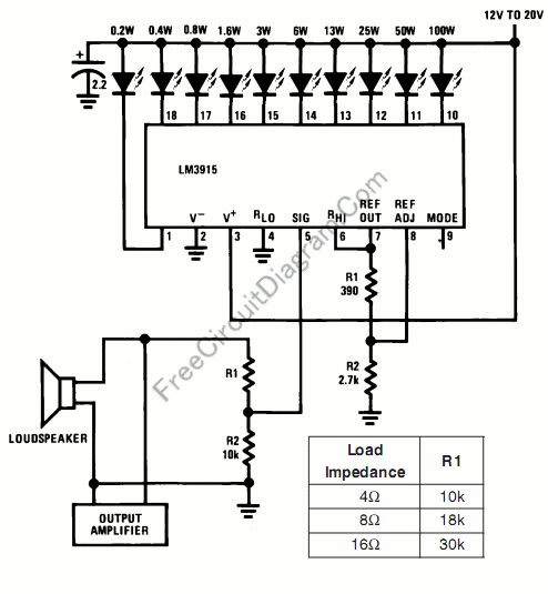
Audio Power Meter: Shows Your Audio Amplifier
This circuit allows for the measurement of the actual output power of an amplifier. It can be housed in a box to function as a measurement instrument.
The circuit for measuring amplifier output power typically includes a few essential components: a...

Audio Simple Sound-to-Light Converter Schematic Diagram
Figure 1 illustrates a simple circuit designed for converting an audio signal (such as one from the output terminals of a CD player). The circuit primarily consists of a buffer/amplifier stage and three filtering circuits: a high-pass filter, a band-pass...

Audio-millivoltmeter
This circuit exhibits a flat frequency response from 8 Hz to 50 kHz, maintaining a -3 dB level at the 10 mV range. Furthermore, while the upper frequency limit remains consistent across less sensitive ranges, the lower frequency limit extends...

Audio Fader
In this circuit, Q1 serves as a simple amplifier with gain control provided by a variable emitter resistance supplied by FET Q2. When switch SI is in the up position, capacitor C3 discharges through resistor R5, resulting in a decrease...

Audio Booster
The circuit diagram represents a booster for an audio application. It features a linear potentiometer R5 with a resistance of 100K ohms, which includes an on/off switch. The capacitor C1 should be selected with a value between 0.05 µF and...

7 Watt Audio Power Amplifier Circuit Schematic
This compact amplifier is built around the TDA2003 integrated circuit, which can deliver 4W RMS at a 4-ohm load. The TDA2003 offers enhanced performance while maintaining the same pin configuration as the TDA2002. It retains the advantageous features of the...