


High-frequency signal output amplifier
#high-frequency
#signal amplifier
#emitter follower
#common collector
#VI3 amplifier
#RF
#transistor
#electronics
#circuit design

Description: A high-frequency signal is displayed in the output amplifier. The circuit consists of a VI3 common collector amplifier (emitter follower) designed to enhance the child-band. It is a high-frequency amplifier (1-250 MHz) that increases the output voltage and boosts the power output stage circuit. This circuit utilizes an emitter, with a signal from high-frequency wideband amplifiers, where VT3 is applied to the base of the circuit in the first stage of the wideband high-frequency amplifier. The design employs a negative power supply, thereby improving the capacity of the pre-wideband high-frequency amplifier.
The described circuit utilizes a common collector configuration, also known as an emitter follower, to achieve impedance matching and provide a high input impedance while maintaining a low output impedance. This configuration is particularly beneficial in high-frequency applications, as it minimizes signal distortion and maximizes bandwidth. The VI3 amplifier is specifically tailored for high-frequency operations, capable of handling frequencies ranging from 1 MHz to 250 MHz, making it suitable for a variety of communication and signal processing applications.
The output stage of the circuit is designed to amplify the voltage signal while ensuring that the power output is significantly increased. This is crucial for applications requiring strong signal transmission over longer distances or through lossy mediums. The use of a negative power supply enhances the performance of the amplifier by allowing for a wider dynamic range and improved linearity, which is essential in high-frequency signal amplification.
In this specific design, the emitter follower configuration allows for the direct application of the output from the high-frequency wideband amplifier (VT3) to the base of the common collector amplifier. This connection facilitates efficient signal transfer and minimizes losses, ensuring that the high-frequency characteristics of the signal are preserved. Additionally, the circuit is optimized for low noise operation, which is a critical factor in high-frequency applications where signal integrity is paramount.
Overall, the combination of a common collector amplifier with a negative power supply and high-frequency design principles results in a robust circuit capable of delivering enhanced performance in various electronic applications.A high frequency signal is shown in the output amplifier, the circuit is constituted by a VI3 common collector amplifier (emitter follower), in order to improve the child-band high-frequency amplifier (1-250 MHz) of the output voltage, increasing the power output stage circuit. This circuit uses emitter, a signal from the high-frequency wideband amplifiers, VT3 applied to the base of the circuit with the first stage of a wideband high frequency amplifier, are performed using negative power supply, thus improving pre-wideband high-frequency amplifier capacity.
The described circuit utilizes a common collector configuration, also known as an emitter follower, to achieve impedance matching and provide a high input impedance while maintaining a low output impedance. This configuration is particularly beneficial in high-frequency applications, as it minimizes signal distortion and maximizes bandwidth. The VI3 amplifier is specifically tailored for high-frequency operations, capable of handling frequencies ranging from 1 MHz to 250 MHz, making it suitable for a variety of communication and signal processing applications.
The output stage of the circuit is designed to amplify the voltage signal while ensuring that the power output is significantly increased. This is crucial for applications requiring strong signal transmission over longer distances or through lossy mediums. The use of a negative power supply enhances the performance of the amplifier by allowing for a wider dynamic range and improved linearity, which is essential in high-frequency signal amplification.
In this specific design, the emitter follower configuration allows for the direct application of the output from the high-frequency wideband amplifier (VT3) to the base of the common collector amplifier. This connection facilitates efficient signal transfer and minimizes losses, ensuring that the high-frequency characteristics of the signal are preserved. Additionally, the circuit is optimized for low noise operation, which is a critical factor in high-frequency applications where signal integrity is paramount.
Overall, the combination of a common collector amplifier with a negative power supply and high-frequency design principles results in a robust circuit capable of delivering enhanced performance in various electronic applications.A high frequency signal is shown in the output amplifier, the circuit is constituted by a VI3 common collector amplifier (emitter follower), in order to improve the child-band high-frequency amplifier (1-250 MHz) of the output voltage, increasing the power output stage circuit. This circuit uses emitter, a signal from the high-frequency wideband amplifiers, VT3 applied to the base of the circuit with the first stage of a wideband high frequency amplifier, are performed using negative power supply, thus improving pre-wideband high-frequency amplifier capacity.

T3SE type 3 SE
The all-transistor T3SE operates similarly to a conventional switch mode power supply (SE). Like the Tritium model, it activates when the charging current falls below a specified threshold. After the circuit is triggered, positive feedback is utilized to latch the...

Wide Dynamic Range Field Strength Meter
A field strength meter is a useful tool for locating a transmitter. However, a sensitive field strength meter has limitations: it responds to nearly any RF signal entering its input. This characteristic reduces the effective sensitivity of the field strength...

SIMPLE DELAY TIMER FOR ONE MINUTE
A simple transistorized one-minute delay timer circuit. It does not include any complex or critical components. This circuit can generate a time delay of approximately one minute. When the switch (preferably a push-button type) is pressed, the LED turns on...

Economical Transistor Radio
The schematic diagram illustrates an audio stage utilizing a common-collector circuit. This configuration does not dampen the tuned circuit; rather, it enhances its response, resulting in improved sensitivity and selectivity. Due to the low supply voltage, the subsequent audio amplifier...

Simple Transistor Amplifier Circuit Schematic and Explanation
This circuit does not function as effectively as it could. It was created when the designer had a limited understanding of circuit design. An improved schematic will be developed and posted later, featuring a better design. The schematic indicates "antenna,"...

easy build motocycle alarm
The circuit requires two transistors to drive a relay, which acts as a switch to activate a buzzer. Any number of normally-open switches may be applied. Mercury switches should be installed to ensure they close when the steering is engaged....

Electronic Horn
Electronic horn circuit diagram. When the power line is switched on, a basic tone is produced by transistor T2 and transformer X1, which is frequency-modulated by a wandering voltage generator affected by a low-frequency square wave generator. This is a...

Multi-Zone Transistor-Based Intruder Alarm
This is a simple transistor-based burglar alarm circuit. Its features include automatic exit and entry delays, along with a timed bell cut-off and reset. It is designed to be used with standard types of normally-closed input devices such as magnetic...
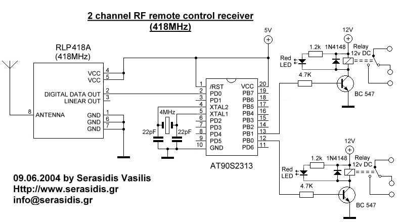
2 channel RF remote control
The basic small-range remote controls are Infrared and RF (Radio Frequency). One of the weaknesses of Infrared is that the signal cannot pass through walls. Therefore, to control a garage door, an RF remote control is necessary. The circuit (transmitter...