


High performance amplifier CD Walkman -TDA1308
#TDA1308
#headphone driver
#class AB
#portable audio
#CD player
#low power consumption
#digital audio
#Philips
#audio amplifier

Description: The TDA1308 is a Class AB headphone driver integrated circuit (IC) recently launched by Philips. Its primary features include a compact size and low power consumption, making it particularly suitable for portable CD players and other digital audio devices. The TDA1308 is designed with a small pin package, and its pin functions are detailed in the accompanying documentation. This IC is equipped with short circuit protection and features a sound switch that does not produce any impact noise. It operates within a voltage range of 3 to 7V, with a unity gain and a conversion rate of 5V/μs. The output power is rated at 60mW, with a signal-to-noise ratio (SNR) of 110dB and channel separation of 70dB. An application circuit for the TDA1308 is also provided in the documentation. Audiophiles can utilize this circuit diagram to replace the conventional VCD player, where the TDA1308 serves as a class-level headphone amplification circuit section, yielding satisfactory results.
The TDA1308 integrated circuit is designed for efficient audio amplification in portable devices, specifically targeting applications where size and power efficiency are paramount. The Class AB configuration allows the TDA1308 to deliver high-quality audio output while minimizing power consumption, which is essential for battery-operated devices. The IC's low quiescent current ensures that it does not drain the battery excessively during idle periods.
The pinout of the TDA1308 is optimized for easy integration into existing designs, allowing engineers to implement it in various audio applications without significant redesign. The short circuit protection feature safeguards the device against potential damage from unintended electrical conditions, enhancing the reliability of the circuit in portable applications.
With an output power of 60mW, the TDA1308 is capable of driving headphones with varying impedance levels, making it suitable for a wide range of audio devices. The impressive signal-to-noise ratio of 110dB indicates that the IC can produce clear audio with minimal background noise, which is critical for high-fidelity sound reproduction. The channel separation of 70dB further ensures that the left and right audio channels remain distinct, providing an immersive listening experience.
The application circuit provided in the documentation illustrates how the TDA1308 can be effectively incorporated into audio systems, including those that replace traditional VCD players. By utilizing the TDA1308 in the headphone amplification section, designers can achieve superior audio performance compared to standard integrated circuits like the 4558. This makes the TDA1308 an attractive option for audio enthusiasts looking to enhance their listening experience with portable audio devices.TDA1308 is class AB headphone driver IC Philips recently launched its biggest feature is the small size, low power consumption, is particularly suitable for portable CD players and other digital audio Xin also be used for CD player headphones listening o TDA1308 adopted by pin small package, the pin function as shown in Figure 5-1 perish TDA1308 equipped with short circuit protection, no impact sound switch, operating voltage 3 ~ 7V, unity gain at the conversion rate of 5V / us.U a sv, foot, -32CI, output power 60mW. SNR llOdB, channel separation 70dBo TDA1308 application circuit shown in Figure 5-2. Hi love hands-enthusiasts can make a circuit diagram t replace the ordinary VCD, only 4558 of the CD player on the low-speed integrated circuits for class-level headphone amplification circuit section, the results are satisfactory.
The TDA1308 integrated circuit is designed for efficient audio amplification in portable devices, specifically targeting applications where size and power efficiency are paramount. The Class AB configuration allows the TDA1308 to deliver high-quality audio output while minimizing power consumption, which is essential for battery-operated devices. The IC's low quiescent current ensures that it does not drain the battery excessively during idle periods.
The pinout of the TDA1308 is optimized for easy integration into existing designs, allowing engineers to implement it in various audio applications without significant redesign. The short circuit protection feature safeguards the device against potential damage from unintended electrical conditions, enhancing the reliability of the circuit in portable applications.
With an output power of 60mW, the TDA1308 is capable of driving headphones with varying impedance levels, making it suitable for a wide range of audio devices. The impressive signal-to-noise ratio of 110dB indicates that the IC can produce clear audio with minimal background noise, which is critical for high-fidelity sound reproduction. The channel separation of 70dB further ensures that the left and right audio channels remain distinct, providing an immersive listening experience.
The application circuit provided in the documentation illustrates how the TDA1308 can be effectively incorporated into audio systems, including those that replace traditional VCD players. By utilizing the TDA1308 in the headphone amplification section, designers can achieve superior audio performance compared to standard integrated circuits like the 4558. This makes the TDA1308 an attractive option for audio enthusiasts looking to enhance their listening experience with portable audio devices.TDA1308 is class AB headphone driver IC Philips recently launched its biggest feature is the small size, low power consumption, is particularly suitable for portable CD players and other digital audio Xin also be used for CD player headphones listening o TDA1308 adopted by pin small package, the pin function as shown in Figure 5-1 perish TDA1308 equipped with short circuit protection, no impact sound switch, operating voltage 3 ~ 7V, unity gain at the conversion rate of 5V / us.U a sv, foot, -32CI, output power 60mW. SNR llOdB, channel separation 70dBo TDA1308 application circuit shown in Figure 5-2. Hi love hands-enthusiasts can make a circuit diagram t replace the ordinary VCD, only 4558 of the CD player on the low-speed integrated circuits for class-level headphone amplification circuit section, the results are satisfactory.

AN12979A Audio Power Amplifier
The AN41240A is a single-chip integrated circuit (IC) designed for audio applications. It employs a single-hall-sensor drive on the input side of the spindle motor drive block and utilizes a low-noise direct PWM drive of sine wave on the output...

sound simple audio amplifier
The sound quality was poor, and then it stopped functioning. Can anyone explain which part of the circuit may have malfunctioned? Any suggestions to enhance the sound quality and restore functionality? The transistors used are both BC546, and the microphone...
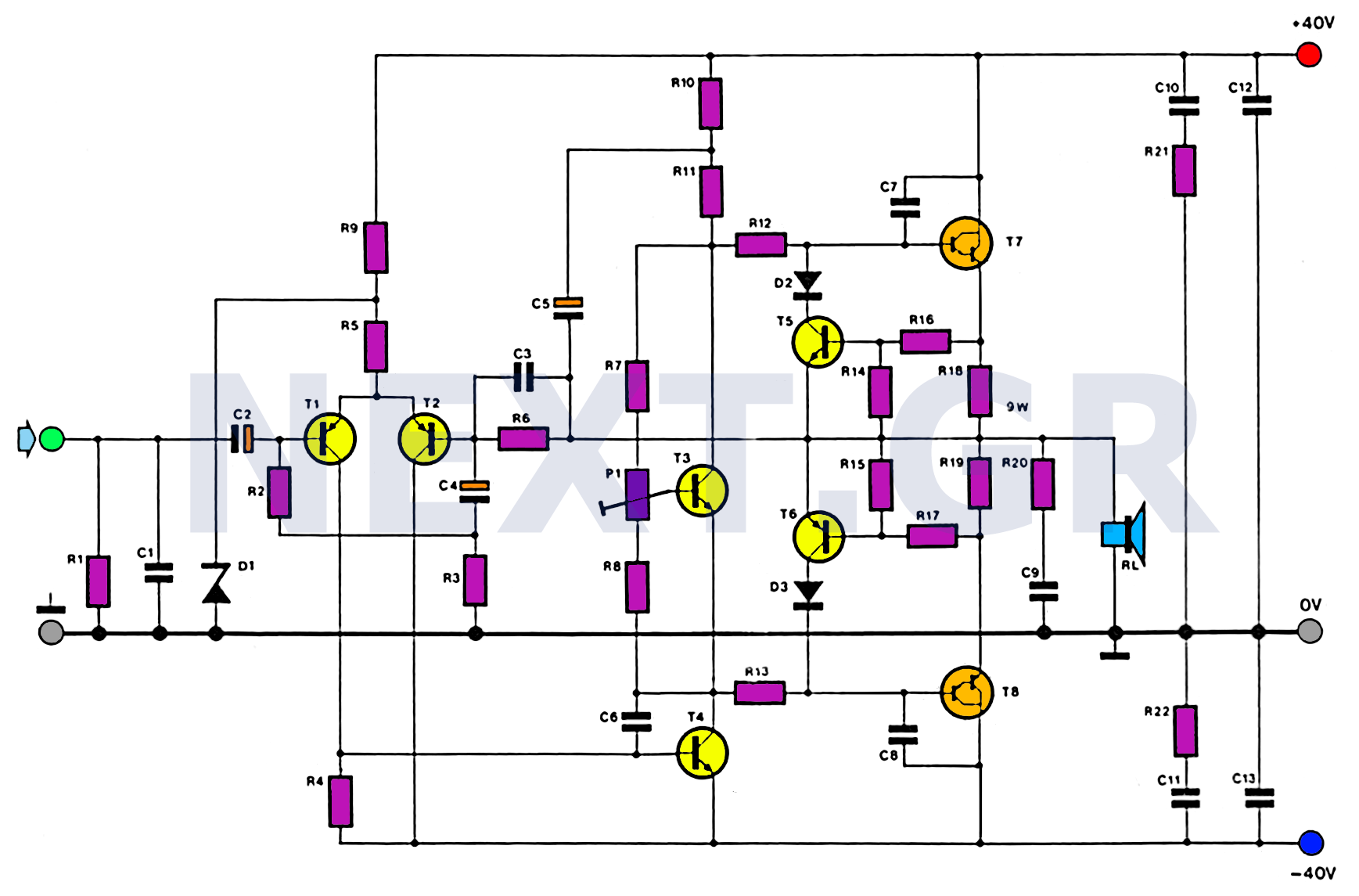
100W HiFi Audio Amplifier Circuit
This amplifier is designed with the following specifications: distortion less than 0.1% at full power of 100W even at 20KHz, with power attributed to an extended bandwidth. The output transistors are protected against short circuits, and the power supply is...
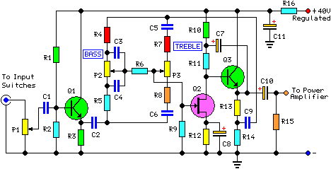
30 Watt Audio Power Amplifier
This project involved the design of an audio amplifier capable of delivering substantial output power with minimal component count while maintaining high quality. The power amplifier section utilizes three transistors along with a few resistors and capacitors in a shunt...

tda7384 class ab audio power amplifier circuit design electronic project
The input capacitor is used for low-frequency cut-off, with a standard value of 0.1 µF, resulting in a cut-off frequency of approximately 16 Hz.
The input capacitor plays a crucial role in filtering unwanted low-frequency signals in electronic circuits. By selecting...

Dual Audio Amplifier Power Supply Circuit
A dual audio amplifier that delivers 50 W per channel is illustrated in the schematic. It features a preamplifier and tone controls, as well as a headphone amplifier. The circuit also shows a power supply providing 38.5 V and 15...

18W Audio Amplifier
High Quality very simple unit - No need for a preamplifier. Can be directly connected to CD players, tuners and tape recorders. Don't exceed 23 + 23V supply. Q3 and Q4 must be mounted on heatsink. D1 must be in...
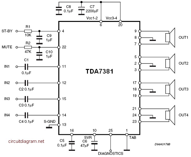
Audio Quad Audio Amplifier Circuit diagram with TDA7831 4G—25W
The amplifier is a quad amplifier circuit (amplifier with four inputs and four outputs) based on the TDA7381. This amplifier is designed for car audio systems, but it can also be utilized for other applications. The circuit has a very...

2 x 220W RMS Audio Amplifier
This amplifier is of such high quality that it would be an understatement to call it a HIFI amplifier. According to HIFI-confirmed-Finland, the frequency response must be direct and distortion <1% 20-20 kHz. Our power amplifier circuit meets the above requirements for bandwidth 5Hz - 500 kHz, however, the frequency band is limited to prevent interference. The amplifier meets the requirements for a reference amplifier, which is suitable for measurement and comparison operations. Small 12-24V voltage system amplifiers operating in the power and properties are somewhat modest, for instance, testing decent speakers. The amplifier is also suitable for demanding PA use.
When music occurs at shallow close 20Hz sound levels, the whole amplifier power reserve may need to be temporarily used. This happens especially when the low-frequency emphasis equalizer or amplifier is used, for example, TV. Watching a movie with lots of sound effects, if the power is not enough in that situation, the sound from the speakers is distorted, reducing the enjoyment of hearing or even damaging the speaker drivers.
The distortion of human hearing range is only about 20 Hz-20 kHz. The hi-fi speaker gamut extends at its best to 25kHz and the hearing area of bats "remains" at 150 kHz, so what are the practical benefits of the amplifier's superior frequency characteristics? The power of less than 1% distortion mentioned in the title 220W blue means the so-called total maximum amount of distortion. This includes TIM distortion (Transient intermodulation) as well as IM-distortion (intermodulation-distortion). TIM distortion occurs in connection with high-speed percussion sounds, such as the sound of dishes on drums. If the amplifier's share of this distortion is high, the amplifier will not be able to play the sound clean, but the sound will be distorted.
The higher the frequencies the amplifier is capable of playing, the less is TIM distortion. If the amplifier would be able to repeat 600 kHz, distortion would not occur at all. IM distortion means that the amplifier generates excess denominated, the so-called undesirable ghost signals. For example, fed in to 19 kHz. And 20 kHz, consists of the difference between 1kHz. Safety Because this amplifier has AC parts, its construction is permitted only in the technical work of teachers. Even in this case, the device should be checked by experts before connecting it to the network. Although the equipment has been revised, it is worth remembering that even the only speaker outputs may at best affect almost 70V the effective voltage.
Therefore, caution is necessary during building and operation. For instance, the speaker terminals should be protected against contact. Building instructions and testing of the amplifier circuit board components will be worth and an amplifier solder test in three stages: 1) The components of the power side, and all the cables signal cables except installed 2) any other circuit board components plus not only hybrid circuit STK 4231 3) STK 4231 placed and cooled, and the input signals the wires connected.
Installation of the power-side components and testing should be done carefully. The transformer wires insulation must first be removed carefully or checked that this has already been done. Then the transformer conductors order is checked on the transformer side.
The circuit board parts include STK4231II Hybrid, Led green, resistors of different values, ceramic and plastic capacitors, a rectifier, fuse holders and fuses, a coil, line voltage parts, potentiometer, RCA connectors, speaker output screws, and a cooling unit.