


Hydrophone Pre-Amplifier
#hydrophone
#low noise
#underwater
#audio
#pre-amplifier
#acoustical
#sensitivity
#impedance matching
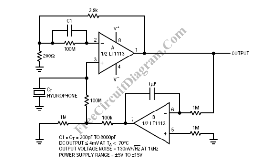
Description: A hydrophone is similar to a microphone, but it is specifically designed for underwater environments. While a hydrophone can also capture sound in air, its sensitivity is reduced because its mechanical-acoustical properties are tailored to match the acoustic impedance of water. The schematic illustrates a low-noise hydrophone amplifier with a DC-servo. One half of the LT1113 (A) is configured as a non-inverting amplifier to boost the voltage signal from the hydrophone, while the other half (B) compensates for current and voltage offset errors from amplifier A. This DC-servo B also eliminates DC errors from the hydrophone output. The capacitance value of C1 should correspond to the hydrophone's capacitance, typically ranging from 200 pF to 8000 pF. The time constant of the servo must exceed that of the hydrophone capacitance and the 100M source resistance to avoid canceling low-frequency signals captured by the hydrophone.
The hydrophone amplifier circuit is essential for enhancing the sensitivity and accuracy of sound detection in aquatic environments. The LT1113 operational amplifier is chosen for its low noise characteristics, which are critical in underwater applications where signal clarity is paramount. The non-inverting configuration utilized in amplifier A ensures that the voltage signal from the hydrophone is amplified without inverting its phase, preserving the integrity of the original sound wave.
The DC-servo mechanism implemented in amplifier B plays a crucial role in maintaining the performance of the hydrophone amplifier. By actively nulling out any DC offsets, it ensures that only the AC signals of interest are amplified, which is vital for detecting subtle sounds in a noisy underwater environment. The choice of capacitor C1 is particularly important; it must be selected based on the hydrophone's specifications to optimize the frequency response and ensure that the amplifier operates effectively within the desired bandwidth.
Furthermore, the time constant of the servo system is a critical design parameter. It must be carefully calculated to be greater than the time constant associated with the hydrophone's capacitance and the high source resistance (100MΩ). This consideration prevents the circuit from filtering out low-frequency signals, which are often the most informative in underwater acoustics.
In summary, the hydrophone amplifier circuit, with its low noise and DC-servo capabilities, is designed to enhance the detection of acoustic signals in underwater environments, making it a vital component in various applications such as marine biology, underwater communication, and environmental monitoring.Hydrophone is similar with microphone, except that it is used in underwater environment. Off course a hydrophone can be used to pick up sound in air, but it will be less sensitive since it`s mechanical-acoustical properties is design to match the acoustical impedance of water. The schematic shows the circuit of a low noise hydrophone amplifier wit h DC-servo. One half of LT1113 (A) is used in non-inverting configuration to amplify the voltage signal from hydrophone, and the other half (B) null the current and voltage offsets error of amplifier A. This DC-servo B also nulls out the DC errors of hydrophone output. The C1 value should match with the hydrophone capacitance, usually between 200 pF and 8000 pF. The servo should have time constant that is larger than the time constant of hydrophone capacitance and the 100M source resistance to prevent canceling the low frequency signal acquired by hydrophone.
[Circuit schematic diagram source: Linear Technology Application Notes] We aim to transmit more information by carrying articles. Please send us an E-mail to wanghuali@hqew. net within 15 days if we are involved in the problems of article content, copyright or other problems.
We will delete it soon.
The hydrophone amplifier circuit is essential for enhancing the sensitivity and accuracy of sound detection in aquatic environments. The LT1113 operational amplifier is chosen for its low noise characteristics, which are critical in underwater applications where signal clarity is paramount. The non-inverting configuration utilized in amplifier A ensures that the voltage signal from the hydrophone is amplified without inverting its phase, preserving the integrity of the original sound wave.
The DC-servo mechanism implemented in amplifier B plays a crucial role in maintaining the performance of the hydrophone amplifier. By actively nulling out any DC offsets, it ensures that only the AC signals of interest are amplified, which is vital for detecting subtle sounds in a noisy underwater environment. The choice of capacitor C1 is particularly important; it must be selected based on the hydrophone's specifications to optimize the frequency response and ensure that the amplifier operates effectively within the desired bandwidth.
Furthermore, the time constant of the servo system is a critical design parameter. It must be carefully calculated to be greater than the time constant associated with the hydrophone's capacitance and the high source resistance (100MΩ). This consideration prevents the circuit from filtering out low-frequency signals, which are often the most informative in underwater acoustics.
In summary, the hydrophone amplifier circuit, with its low noise and DC-servo capabilities, is designed to enhance the detection of acoustic signals in underwater environments, making it a vital component in various applications such as marine biology, underwater communication, and environmental monitoring.Hydrophone is similar with microphone, except that it is used in underwater environment. Off course a hydrophone can be used to pick up sound in air, but it will be less sensitive since it`s mechanical-acoustical properties is design to match the acoustical impedance of water. The schematic shows the circuit of a low noise hydrophone amplifier wit h DC-servo. One half of LT1113 (A) is used in non-inverting configuration to amplify the voltage signal from hydrophone, and the other half (B) null the current and voltage offsets error of amplifier A. This DC-servo B also nulls out the DC errors of hydrophone output. The C1 value should match with the hydrophone capacitance, usually between 200 pF and 8000 pF. The servo should have time constant that is larger than the time constant of hydrophone capacitance and the 100M source resistance to prevent canceling the low frequency signal acquired by hydrophone.
[Circuit schematic diagram source: Linear Technology Application Notes] We aim to transmit more information by carrying articles. Please send us an E-mail to wanghuali@hqew. net within 15 days if we are involved in the problems of article content, copyright or other problems.
We will delete it soon.

Audio Oscillator Ii
The circuit's frequency oscillation is given by the formula f = 2.8 / [Cix(i1 + i2)]. By utilizing the specified values, the output frequency can be adjusted from 60 Hz to 20 kHz by rotating potentiometer R2. A portion of...

Audio VU meter with Extra wide Dynamic Range 69 dB using Arduino
After experimenting with a stereo version of the VU meter described in a previous blog post, a studio-grade VU meter is now being presented. This meter features 24 steps, spaced equally every 3 dB, and covers a wide dynamic range...
Automatic Loudness Control
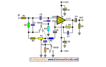
Simple add-on module, Switchable "Control-flat" option. In order to obtain good audio reproduction at different listening levels, a different tone control...
The described module is a straightforward add-on designed to enhance audio reproduction across various listening levels. The "Control-flat" option allows...

Audio power Amplifier Tester Dummy load
If you want to test an amplifier, a dummy load may be more convenient for speakers to use than actual speakers, due to noise or damage to the speakers. This circuit behaves in terms of impedance and frequency response as...

Audio Shunt Noise Limiter
Examples of RF and audio ANL circuits. Positive and negative clipping occurs in both circuits. The circuit is self-adjusting. This noise limiter operates at the IF output. Adequate gain is needed at the IF frequency so that several volts peak-to-peak...

Mini Audio Booster Amplifier
This small amplifier circuit is ideal for boosting small audio units.
The small amplifier circuit is designed to enhance the audio signals from low-output devices, such as microphones or portable music players. It typically employs a transistor or an operational amplifier...

50W Audio Amplifier Circuit
An audio amplifier is an electronic device designed to amplify low-power audio signals, which primarily consist of frequencies ranging from 20 Hz to 20,000 Hz, the human range of hearing. This amplification is necessary to drive loudspeakers and represents the...

Simple Hybrid Audio Amplifier
The ongoing debate regarding the superiority of valves versus transistors is not the focus here. However, for those uncertain about their choice, this simple amplifier serves as an excellent experiment. The design employs a valve as a pre-amplifier and a...

HA13118 IC For 18W Car Stereo Amplifier
This is a Class AB audio power amplifier utilizing the Hitachi HA13118 module, suitable for car applications. It can also be used in various other settings.
The Class AB audio power amplifier is designed to deliver high-quality sound reproduction while maintaining...