


I.F. Amplifier

Description: The I.F. amplifier is similar to the one used in the 80M receiver project. The original design has been modified by putting a couple of LEDs in the source circuit of each MOSFET. The voltage drop across the LEDs keeps the source voltage at about two volts. This results in a much greater AGC range. This arrangement was suggested by N6BIU. Thanks, Jim. The I.F. transformer primary has 18 turns, the secondary winding has 4 turns.
The Intermediate Frequency (I.F.) amplifier described is a critical component in radio receiver systems, particularly for the 80M band. The modification involving the inclusion of Light Emitting Diodes (LEDs) in the source circuit of each MOSFET is notable for enhancing the performance of the amplifier. The LEDs introduce a fixed voltage drop, stabilizing the source voltage at approximately 2 volts. This stabilization is essential for achieving a broader Automatic Gain Control (AGC) range, which is crucial for maintaining signal integrity across varying input levels.
In this design, the I.F. transformer plays a pivotal role in signal processing. The primary winding consists of 18 turns, while the secondary winding features 4 turns. This specific turn ratio is indicative of the desired impedance transformation and voltage gain characteristics of the amplifier. The 18:4 turn ratio implies that the primary winding is designed to handle a higher voltage from the preceding stages, while the secondary winding steps down the voltage to a level suitable for further amplification or processing.
The choice of MOSFETs in this I.F. amplifier design is likely due to their high input impedance and fast switching capabilities, which are advantageous in high-frequency applications. The incorporation of the LEDs not only aids in voltage stabilization but also potentially provides visual feedback for circuit operation, allowing for easier troubleshooting and performance monitoring.
Overall, the modifications and design choices made in this I.F. amplifier reflect a thoughtful approach to enhancing receiver performance, ensuring that it can effectively manage signal variations and maintain clarity in communication.The I.F. amplifier is similar to the one used in the 80M receiver project . The original design has been modified by putting a couple of LED`s in the source circuit of each Mosfet. The voltage drop across the LED`s keeps the source voltage at about two volts. This results in a much greater AGC range. This arrangement was suggested by N6BIU. Thanks Jim. The I.F. transformer primary has 18 turns, the secondary winding has 4 turns.
The Intermediate Frequency (I.F.) amplifier described is a critical component in radio receiver systems, particularly for the 80M band. The modification involving the inclusion of Light Emitting Diodes (LEDs) in the source circuit of each MOSFET is notable for enhancing the performance of the amplifier. The LEDs introduce a fixed voltage drop, stabilizing the source voltage at approximately 2 volts. This stabilization is essential for achieving a broader Automatic Gain Control (AGC) range, which is crucial for maintaining signal integrity across varying input levels.
In this design, the I.F. transformer plays a pivotal role in signal processing. The primary winding consists of 18 turns, while the secondary winding features 4 turns. This specific turn ratio is indicative of the desired impedance transformation and voltage gain characteristics of the amplifier. The 18:4 turn ratio implies that the primary winding is designed to handle a higher voltage from the preceding stages, while the secondary winding steps down the voltage to a level suitable for further amplification or processing.
The choice of MOSFETs in this I.F. amplifier design is likely due to their high input impedance and fast switching capabilities, which are advantageous in high-frequency applications. The incorporation of the LEDs not only aids in voltage stabilization but also potentially provides visual feedback for circuit operation, allowing for easier troubleshooting and performance monitoring.
Overall, the modifications and design choices made in this I.F. amplifier reflect a thoughtful approach to enhancing receiver performance, ensuring that it can effectively manage signal variations and maintain clarity in communication.The I.F. amplifier is similar to the one used in the 80M receiver project . The original design has been modified by putting a couple of LED`s in the source circuit of each Mosfet. The voltage drop across the LED`s keeps the source voltage at about two volts. This results in a much greater AGC range. This arrangement was suggested by N6BIU. Thanks Jim. The I.F. transformer primary has 18 turns, the secondary winding has 4 turns.

508A microcontroller can deliver a maximum of 25mA
A typical device that requires less than 5v and draws less than 25mA is an LED. A LED must be supplied with an exact voltage for it to operate correctly. Because it requires LESS than 5v, a dropper resistor (current...

MOSFET Toggle Switching circuit
This circuit was adapted from the Toggle Switch Debounced Pushbutton by John Lundgren. It is useful where the load needs to be switched on from one location and switched off from another. Any number of momentary (N/O) switches or push...

Color Sensor from a Reversed LED and Op Amp
One of the first lessons that electronics students learn is that an LED emits light when current flows through it. However, it is also true that when an LED is connected in reverse, it can generate a current flow when...
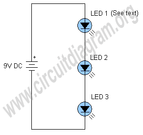
simplest led flasher
The schematic below illustrates a simple LED flasher circuit. This circuit utilizes three LEDs that begin to blink or flash upon receiving a 9-volt supply. It is straightforward in design, employing a self-flashing LED (LED 1) to trigger the flashing...

72 led clock
The circuit utilizes 60 individual LEDs to represent the minutes of a clock and 12 LEDs to indicate the hours. The power supply and timing circuitry are consistent with those outlined in the previous 28 LED clock circuit. The minutes...

LED Chaser
I don't know why, but people like blinking lights. You see LED chasers everywhere, in TV shows (Knight Rider), movies, and store windows. This schematic is my version of a simple 10 LED chaser. There is no 555 timer used...

Electrical transformer tutorial
Afroman explains the fundamentals of transformer operation, where to purchase step-down mains transformers, and how to safely wire one to mains voltages. The discussion includes both European and North American wiring standards. The presentation concludes with a brief example of...

Blinker Indicator
When the lamp turns off, a reset pulse is generated for the corresponding counter by NAND gate IC1. The counter then counts up again. The display's progression rate can be adjusted to the desired speed using potentiometer P1. Only one...

led lighting management ic improves power factor and efficiency
There is significant sensitivity to operating costs when managing high-powered commercial lighting. In these applications, there is a heightened focus on energy efficiency and AC line power factor, as these parameters influence operating expenses. Electric utilities impose additional charges on...