


making of 6ah4 line stage circuit
#line stage
#preamp
#power supply
#audio amplifier
#tube amplifier
#circuit assembly
#Octal preamplifier
#audio signal
#electronics project
#DIY audio

Description: The circuit and assembly process of the line stage is presented in two separate articles. This linestage shares the same circuit as the two chassis version previously described. However, in this design, the power supply and preamplifier are housed together in a single enclosure that matches the style of the power amplifier it is intended to drive. The circuit is fundamentally the linestage section of the Octal preamplifier Mk2. The only distinction lies in the heater supply, which can be AC since this is exclusively a line-level preamp. The transformer volume controls (TVCs) utilize 24*2 dB/step autoformer modules from Intact Audio. The volume control and input selection switches are Swiss-made components from Elma. All capacitors employed are ASC MP oil types, with no electrolytics used. The sole amplifying component is a 6AH4GT triode per channel, characterized as a low mu triode with low plate resistance. This configuration, combined with a 3.5:1 step-down, results in a very low output impedance, which is adequate for driving a TVC and long cables to the power amplifier. Similar to the 6CB5 amplifier, a hybrid rectifier bridge is utilized, featuring UF4007 diodes alongside 6AX4 tube dampers. Each leg of the rectifier includes two diodes in series to manage substantial peak inverse voltages that may arise in a choke input filter supply. The power transformer is of the same type as that used in the power amplifier but is smaller due to the preamp's reduced current draw. This transformer incorporates grain-oriented core laminations and dual electrostatic screens between the primary and secondary windings. Additionally, a flux band surrounds the outer portion of the winding stack. The output is designed to float, allowing for differential connection to the power amplifier. One side is connected to ground via a 1M resistor to prevent static charge buildup in the output, which could create a popping sound when plugged in while the power amplifier is powered on. The heater supply for the 6AH4 is referenced to ground through two 100 Ohm resistors.
The circuit design features a robust yet straightforward architecture that emphasizes audio fidelity and component quality. The choice of a low mu triode, such as the 6AH4GT, ensures that the preamp maintains a low output impedance, which is crucial for interfacing with the transformer volume controls and maintaining signal integrity over long cable runs. The absence of electrolytic capacitors in the signal path is a deliberate design choice aimed at enhancing audio performance, as film capacitors typically offer superior sonic characteristics.
The hybrid rectifier bridge configuration combining solid-state diodes with vacuum tube dampers is particularly advantageous in this application, as it balances the fast response of silicon diodes with the smoothness of tube rectification. This results in improved transient response and overall sound quality. The power transformer design, featuring grain-oriented laminations and electrostatic shielding, minimizes electromagnetic interference and enhances the efficiency of the power supply, which is critical in high-fidelity audio applications.
The floating output design facilitates a differential connection to the power amplifier, which is essential for reducing noise and interference. The inclusion of a 1M resistor to ground is a precautionary measure to mitigate any static charge that may accumulate, thus ensuring a smooth power-up sequence and preventing audible disturbances. The heater supply's grounding through two 100 Ohm resistors further stabilizes the circuit, contributing to the overall reliability and performance of the preamplifier.
In summary, this line stage circuit exemplifies high-quality audio engineering, integrating carefully selected components and innovative design features to deliver exceptional performance in a compact and aesthetically cohesive package.Circuit and assembly process of the line stage in two separate articles. The linestage shares the same circuit with the two chassis version which was already presented. Only this time power supply and preamp will be in one housing which will be in the same style as the power amp it is supposed to drive. The circuit is basically the linestage section of my Octal preamplifier Mk2. The only difference is in the heater supply, which can be AC since this is a linelevel preamp only. The TVCs are done with 24*2 db/step autoformer modules from intactaudio. Volume control and input select switches are swiss made from Elma. All capacitors are ASC MP in oil types. No electrolytics. The only amplifying element is a 6AH4GT triode per channel. This is a low mu triode with low plate resistance. With the 3. 5:1 step down this yields a very low output impedance, more than suitable to drive a TVC and long cables to the power amp. As in the 6CB5 amp, a hybrid rectifier bridge was chosen. UF4007 diodes complement the 6AX4 TV dampers. Two diodes are in series in each leg, since substantial peak inverse voltages can occur in a choke input filter supply.
The power transformer is of the same type as the one used in the power amp. Only a smaller version since the preamp has much less current draw. The power transformer has grain oriented core laminations and dual electrostratic screens between primary and secondaries. In addition there is a flux band around the outside of the winding stack. The output is basically floating to allow differential connection to the power amp. One side is connected to ground through a 1M resistor to avoid static charge build up in the output which could cause a plop when plugged in while power amp is turned on.
The heater supply of the 6AH4 is referenced to ground through 2 100 Ohm resistors.
The circuit design features a robust yet straightforward architecture that emphasizes audio fidelity and component quality. The choice of a low mu triode, such as the 6AH4GT, ensures that the preamp maintains a low output impedance, which is crucial for interfacing with the transformer volume controls and maintaining signal integrity over long cable runs. The absence of electrolytic capacitors in the signal path is a deliberate design choice aimed at enhancing audio performance, as film capacitors typically offer superior sonic characteristics.
The hybrid rectifier bridge configuration combining solid-state diodes with vacuum tube dampers is particularly advantageous in this application, as it balances the fast response of silicon diodes with the smoothness of tube rectification. This results in improved transient response and overall sound quality. The power transformer design, featuring grain-oriented laminations and electrostatic shielding, minimizes electromagnetic interference and enhances the efficiency of the power supply, which is critical in high-fidelity audio applications.
The floating output design facilitates a differential connection to the power amplifier, which is essential for reducing noise and interference. The inclusion of a 1M resistor to ground is a precautionary measure to mitigate any static charge that may accumulate, thus ensuring a smooth power-up sequence and preventing audible disturbances. The heater supply's grounding through two 100 Ohm resistors further stabilizes the circuit, contributing to the overall reliability and performance of the preamplifier.
In summary, this line stage circuit exemplifies high-quality audio engineering, integrating carefully selected components and innovative design features to deliver exceptional performance in a compact and aesthetically cohesive package.Circuit and assembly process of the line stage in two separate articles. The linestage shares the same circuit with the two chassis version which was already presented. Only this time power supply and preamp will be in one housing which will be in the same style as the power amp it is supposed to drive. The circuit is basically the linestage section of my Octal preamplifier Mk2. The only difference is in the heater supply, which can be AC since this is a linelevel preamp only. The TVCs are done with 24*2 db/step autoformer modules from intactaudio. Volume control and input select switches are swiss made from Elma. All capacitors are ASC MP in oil types. No electrolytics. The only amplifying element is a 6AH4GT triode per channel. This is a low mu triode with low plate resistance. With the 3. 5:1 step down this yields a very low output impedance, more than suitable to drive a TVC and long cables to the power amp. As in the 6CB5 amp, a hybrid rectifier bridge was chosen. UF4007 diodes complement the 6AX4 TV dampers. Two diodes are in series in each leg, since substantial peak inverse voltages can occur in a choke input filter supply.
The power transformer is of the same type as the one used in the power amp. Only a smaller version since the preamp has much less current draw. The power transformer has grain oriented core laminations and dual electrostratic screens between primary and secondaries. In addition there is a flux band around the outside of the winding stack. The output is basically floating to allow differential connection to the power amp. One side is connected to ground through a 1M resistor to avoid static charge build up in the output which could cause a plop when plugged in while power amp is turned on.
The heater supply of the 6AH4 is referenced to ground through 2 100 Ohm resistors.

16 watt amplifier
This circuit provides 16 watts of amplification. It is built using two LM383 power audio amplifiers. Use suitable heat sinks with the ICs. More: U1 U2 LM383 8 watt audio amplifier IC R1, R3 220 ohm resistor R2, R4 2.2...

200 Watt High Quality Audio Amplifier
This high-power audio amplifier provides top-quality performance for loudspeakers with an impedance of 4 to 8 ohms. It operates within a frequency range of 20 to 20,000 Hz and requires a voltage supply of 24 to 36 volts, with a...

600 watt audio amplifier (LM4702)
The circuit is based around LM4702 manufactured by NATIONAL semiconductors MJ11029-MJ11028 by ON semiconductors. It is a high fidelity audio power amplifier designed for demanding consumer and pro-audio applications. You can also use this circuit with AV receivers, audiophile power...
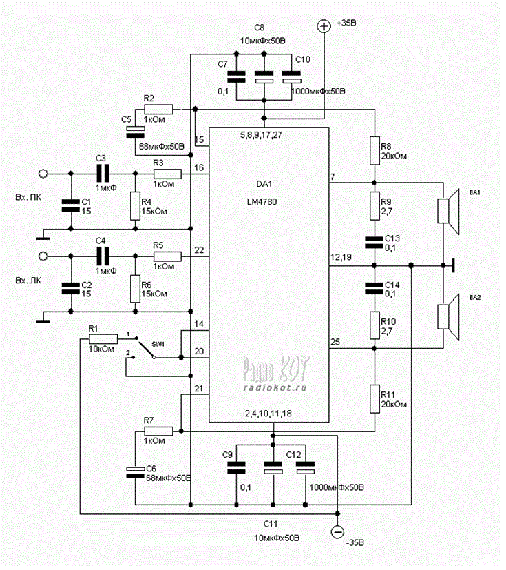
audio amplifier using ic lm4780
Explore the power amplifier integrated circuit from National Semiconductor, the LM4780. What is noteworthy about this component is its very low harmonic distortion. Typically, manufacturers specify the maximum power of their products with a harmonic content of around 10%. However,...

30W Power Audio Amplifier Circut
TIP141 is an NPN silicon power Darlington transistor designed for complementary use with TIP145, TIP146, and TIP147. It can handle up to 125 W at a case temperature of 25 °C, with a continuous collector current of 10 A and...

14 Watt Audio Amplifier
The audio amplifier shown below provides 14 watts of power, but can provide much more simply by increasing the power supply voltage. This amp was built in 1975 and has worked reliably ever since. The power amp portion was published...
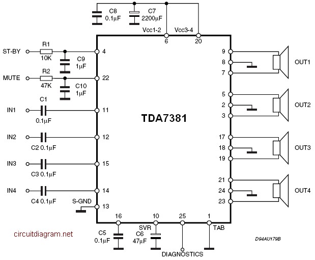
Audio Quad Audio Amplifier Circuit diagram with TDA7831 4G—25W
The amplifier is a quad amplifier circuit (amplifier with four inputs and four outputs) based on the TDA7381. This amplifier is designed for car audio systems, but it can also be utilized for other applications. The circuit has a very...

preamp
This is a clean preamp designed for use with a bass, a power amplifier, and a cabinet in a rehearsal space. The preamp is a unique design, developed from the ground up. The initial concept was an all-transistor design utilizing...

TDA7056 audio amplifier circuit diagram electronic project
This TDA7056 power audio amplifier circuit diagram project is designed to deliver a maximum output power of 1 watt into an 8-ohm load when powered by a 6-volt supply, or a maximum output power of 3 watts into a 16-ohm...