


Motorola Hi-Fi power amplifier

Description: This is a straightforward, cost-effective Hi-Fi quality power amplifier. It can be constructed in five different configurations, as indicated in the table, ranging from 20 W to 80 W RMS.
This Hi-Fi quality power amplifier is designed to deliver high audio fidelity while maintaining affordability. The amplifier's versatility allows for five distinct configurations, enabling users to select the appropriate power output based on their specific requirements. The output power options range from 20 W to 80 W RMS, accommodating various speaker systems and listening environments.
The circuit typically comprises a differential input stage, which enhances common-mode rejection and improves overall sound quality. Following this, a voltage amplification stage boosts the signal before it reaches the output stage, which is responsible for driving the load. The output stage may utilize transistors or integrated circuits, depending on the selected configuration, to achieve the desired power output.
To ensure optimal performance, the amplifier includes various feedback mechanisms that stabilize the gain and reduce distortion. Additionally, power supply considerations are crucial; a well-regulated power supply with appropriate filtering will significantly influence the amplifier's performance and noise levels.
Thermal management is also an important aspect of the design, as power amplifiers can generate substantial heat during operation. Adequate heat sinking and ventilation must be incorporated to prevent overheating and ensure reliable operation over extended periods.
Overall, this power amplifier design offers flexibility, efficiency, and high-quality audio reproduction, making it suitable for a wide range of audio applications.This is a very simple, low cost, Hi-Fi quality power amplifier. You can build it 5 ways, like its shown in the table (from 20 W to 80 W RMS)..
This Hi-Fi quality power amplifier is designed to deliver high audio fidelity while maintaining affordability. The amplifier's versatility allows for five distinct configurations, enabling users to select the appropriate power output based on their specific requirements. The output power options range from 20 W to 80 W RMS, accommodating various speaker systems and listening environments.
The circuit typically comprises a differential input stage, which enhances common-mode rejection and improves overall sound quality. Following this, a voltage amplification stage boosts the signal before it reaches the output stage, which is responsible for driving the load. The output stage may utilize transistors or integrated circuits, depending on the selected configuration, to achieve the desired power output.
To ensure optimal performance, the amplifier includes various feedback mechanisms that stabilize the gain and reduce distortion. Additionally, power supply considerations are crucial; a well-regulated power supply with appropriate filtering will significantly influence the amplifier's performance and noise levels.
Thermal management is also an important aspect of the design, as power amplifiers can generate substantial heat during operation. Adequate heat sinking and ventilation must be incorporated to prevent overheating and ensure reliable operation over extended periods.
Overall, this power amplifier design offers flexibility, efficiency, and high-quality audio reproduction, making it suitable for a wide range of audio applications.This is a very simple, low cost, Hi-Fi quality power amplifier. You can build it 5 ways, like its shown in the table (from 20 W to 80 W RMS)..

KIA7217AP 5.8W AUDIO POWER AMPLIFIER. CAR STEREO CAR RADIO OUTPUT
The UTC L2572 is a wideband PLL FM demodulator designed primarily for use in satellite tuners. It incorporates all essential components, except for the loop feedback elements, to create a complete PLL system capable of operating at frequencies up to...

Hi-fi amplifier 80Wx2
The 2SC2987 and 2SA1227 transistors are used in the uPC1342V circuit, which is a two-channel high-power amplifier capable of delivering 80W using two tubes in the discharge circuit. This circuit incorporates a multifunction protection feature similar to the PC1237 circuit....
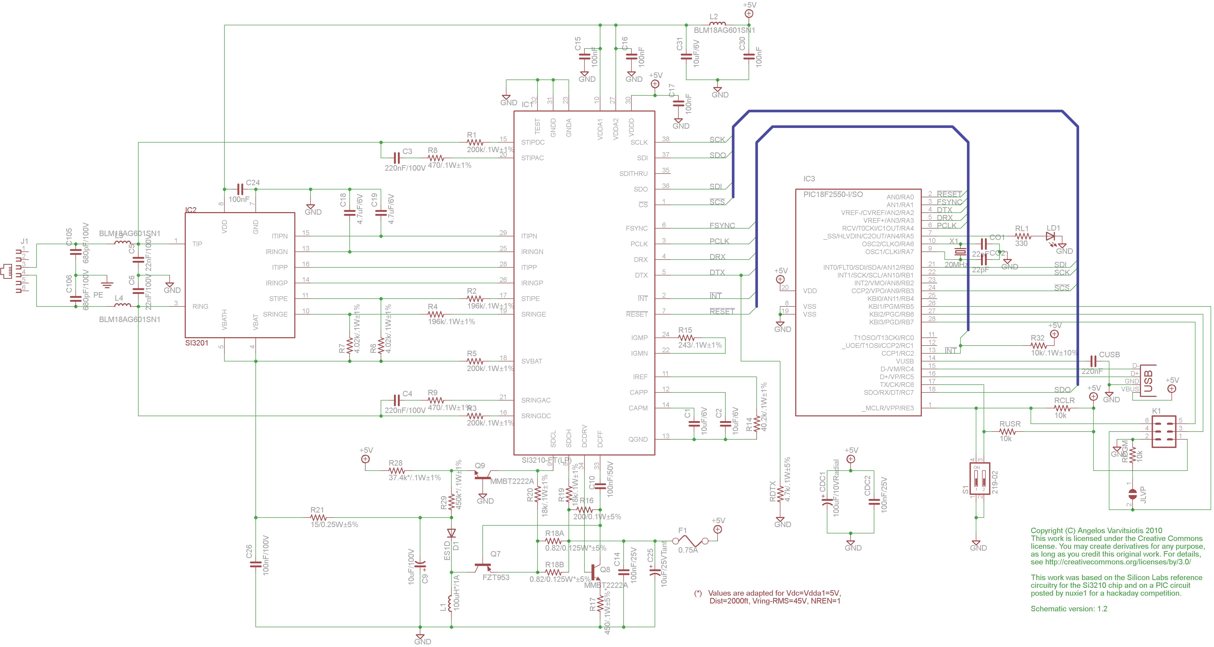
dyi setup and debugging guide
This page discusses the differences between assembled Open USB FXS dongle boards and DIY boards. While the assembled boards are fully tested and quality control approved, DIY boards may encounter various issues during assembly. Fortunately, most of these issues can...

40 Watt Audio power Amplifier LM3876
This Circuit is based on the LM3876. A 11-pin plastic package IC with high performance audio power amplifier, an output mute function which can be used to eliminate switch-on and switch-off "thumps" to the loudspeaker load. It is capable of...

Variable_audio_oscillator_with_a_range_of_20_hertz_to_20_kilohertz
A variable audio oscillator operates within a frequency range of 20 hertz to 20 kilohertz. The circuit utilizes an Intersil 8038 waveform generator, which is designed in a 14-pin dual in-line package (DIP).
The variable audio oscillator circuit is designed to...

Simple structure hi-fi amplifier
The circuit illustrated in Figure 240 is straightforward, utilizing only four transistors to process the input voltage, resulting in a large, inverted output. This configuration serves as a high-performance amplifier, delivering excellent high-fidelity power discharge capabilities. The input stage employs...

Low distortion audio gain limiter
The level at which the limiter activates in audio can be adjusted using the LIMIT LEVEL selector knob. When this threshold is surpassed, the output of the half-limiting detector within the op-amp, functioning as a comparator, triggers the LED, leading...

Bridging Adapter For Power Amplifiers
A stereo power amplifier is limited in its output power by two main factors - the impedance of the load and the internal power supply voltage. To obtain more power, one has very limited choices - other than the purchase...

Klipsch Promedia V5.1 Amplifier Repair
Utilize a V2-400 subwoofer amplifier for the center channel, and incorporate a separate Digital Converter specifically for the added subwoofer amplifier to initiate a V5.1 system. Place all preamplifiers within the subwoofer enclosure and design a digital control box for...