


Odd-ball PI circuit identification request and headroom question
#guitar amplifier
#6v6 tubes
#12AU7
#paraphase inverter
#headroom
#clipping
#vacuum tube
#audio amplifier
#Bell & Howell
#projector amp

Description: This schematic has been modified from an old Bell & Howell projector amplifier for model 302, utilizing PP 6V6 tubes with a 12AU7 phase inverter (PI). The PI circuit appears to be closest to a "floating paraphase." There is a desire for increased clean headroom and volume, as the current setup produces clipping at about one-third of the volume when driven by a guitar. The distortion is perceived as musically pleasing, which prevents a switch to a long-tail pair (LTP) or another type of PI. The aim is to achieve a "drummer-friendly" volume without excessive crunch, ideally maintaining a usable clean volume while employing a boost pedal to achieve saturation. Although specific voltage specifications are not available, a sine wave at 1V RMS was sent through the amp, revealing that the PI distorts before any preamp stages reach saturation. There is an indication that the clipping occurs equally in both positive and negative voltage swings of the sine wave. Suggestions include decreasing the dropping resistor to increase the PI supply voltage for more headroom, and potentially rebiasing each cathode to accommodate higher plate voltages. There is also consideration to reduce the 10k resistor while compensating by increasing a subsequent resistor to maintain downstream voltage levels. The circuit has an error with a bridged resistor (the output screen resistor), and the tone stack is receiving signal through a 0.05 coupling capacitor instead of the values mentioned. Voltages are reported to be fairly accurate, with plans to raise the plate voltage on the output section to at least 350V, pending the appropriate cathode resistor for safety. Observations on the oscilloscope confirmed that the sine wave at 1V RMS remained clear at all preamp stages, but distortion occurred at the output tubes' grid, which is typical for clipping in a well-designed amplifier.
The output stage of the amplifier employs a pair of 6V6 tubes in a push-pull configuration, which is common for delivering a warm, rich tone. The 12AU7 phase inverter is crucial for converting the single-ended signal from the preamp into a differential signal suitable for driving the output tubes. The "floating paraphase" design allows for a balanced output with reduced distortion, though the need for additional headroom is evident.
In the context of enhancing clean headroom, reducing the dropping resistor can effectively increase the voltage supplied to the PI, thereby improving the dynamic range before distortion occurs. This adjustment necessitates careful consideration of the subsequent resistor values to maintain the overall circuit balance and prevent unintended biasing issues in the following stages.
Rebiasing the cathodes of the output tubes can also be an effective strategy, allowing for higher plate voltages without compromising the integrity of the signal. It is essential to ensure that the output stage remains within safe operating limits to avoid damage to the tubes. The mention of observing the clipping behavior on an oscilloscope indicates a methodical approach to diagnosing the performance of the amplifier and understanding the interaction between different stages.
The circuit also features a tone stack designed with standard Baxandall values, which is known for its effectiveness in shaping the tonal characteristics of an amplifier. The use of a coupling capacitor to isolate the tone stack from the preceding stage is crucial for preventing unwanted frequency interactions and ensuring a clean signal path.
Overall, the modifications and observations made on this schematic reflect a thoughtful approach to achieving a desirable sound while navigating the complexities of amplifier design. Further experimentation and fine-tuning may yield the desired results, enhancing both the clean and distorted tones of the amplifier.This schematic is modified from an old Bell & Howell projector amp for model 302 - PP 6v6`s with a 12AU7 PI. Can anyone identify the PI circuit It appears closest to "floating paraphase" to me. My only complaint with this circuit is that I`d like more clean headroom/volume. Driving it with a guitar, I`m getting clipping at about 1/3 of the way up on the volume. The clipping/distortion itself is pretty musical to me - that keeps me from switching to LTP or some other type of PI. But I`m looking to get a more "drummer friendly" volume from the amp without being slaved to a ton of crunch - idealy I would have a workable "clean" volume and then hit a boost pedal to push it into saturation.
I don`t have all the specs of actual voltages and such to provide, but I did send a sine wave at 1v rms through the amp and found that the PI is distorting well before any Preamp stages - I don`t even know that the preamp reaches saturation/clipping. Hey Soundguruman - thanks for the attempt - it could be diyAudio, as I can see the schematic from here (a different computer than the original post) and diyAudio is going super-slow for me right now.
That is the dropping resistor that can be decreased, causing the PI supply to go higher in constant voltage. causing the available headroom to be realized. Checking each stage with the o scope, you "could"see that the clipping of the stage is equal in both positive and negative voltage swing of the sine wave.
"could" Rebias each cathode to accommodate a higher plate voltage, when you get it up there high enough. Thanks for the suggestions. I thought of lessening the 10k, and of compensating to keep the voltage "downstream" the same by raising the next resistor by the same amount so that I don`t have to rebias other stages.
I guess I just wondered if there was some obvious other issue that could be tweaked. I saw "floating paraphase" as an possible description of the circuit, but each example I`ve found online had an additional stage of 1m resistors between PI and output. that`s what struck me as odd-ball about this one. however, i`ve still a lot to learn. here`s the complete schematic, though it has an error where there is a bridged resistor (actually the output screen resistor) and also ignore the red values in the tone stack, I went with standard bax values for now - oh and the tone stack is receiving signal through a.
05 coupling cap instead of either value mentioned. voltages are fairly accurate. i plan to raise the plate voltage on the output section to at least 350 but don`t yet have the appropriate cathode resistor to make it safe. verified on the `scope - sine wave at 1v rms was still clearly a sine wave at all preamp stages, but distorted at the grid of the output tubes - just after the PI This is actually the normal condition for clipping in a well designed amp.
The output tubes` grids conduct above about 0 volts grid-to-cathode, clipping the preceding stage. An interesting test is to pull out the output tubes and see if a larger voltage can then be made at their grid pins.
The output stage of the amplifier employs a pair of 6V6 tubes in a push-pull configuration, which is common for delivering a warm, rich tone. The 12AU7 phase inverter is crucial for converting the single-ended signal from the preamp into a differential signal suitable for driving the output tubes. The "floating paraphase" design allows for a balanced output with reduced distortion, though the need for additional headroom is evident.
In the context of enhancing clean headroom, reducing the dropping resistor can effectively increase the voltage supplied to the PI, thereby improving the dynamic range before distortion occurs. This adjustment necessitates careful consideration of the subsequent resistor values to maintain the overall circuit balance and prevent unintended biasing issues in the following stages.
Rebiasing the cathodes of the output tubes can also be an effective strategy, allowing for higher plate voltages without compromising the integrity of the signal. It is essential to ensure that the output stage remains within safe operating limits to avoid damage to the tubes. The mention of observing the clipping behavior on an oscilloscope indicates a methodical approach to diagnosing the performance of the amplifier and understanding the interaction between different stages.
The circuit also features a tone stack designed with standard Baxandall values, which is known for its effectiveness in shaping the tonal characteristics of an amplifier. The use of a coupling capacitor to isolate the tone stack from the preceding stage is crucial for preventing unwanted frequency interactions and ensuring a clean signal path.
Overall, the modifications and observations made on this schematic reflect a thoughtful approach to achieving a desirable sound while navigating the complexities of amplifier design. Further experimentation and fine-tuning may yield the desired results, enhancing both the clean and distorted tones of the amplifier.This schematic is modified from an old Bell & Howell projector amp for model 302 - PP 6v6`s with a 12AU7 PI. Can anyone identify the PI circuit It appears closest to "floating paraphase" to me. My only complaint with this circuit is that I`d like more clean headroom/volume. Driving it with a guitar, I`m getting clipping at about 1/3 of the way up on the volume. The clipping/distortion itself is pretty musical to me - that keeps me from switching to LTP or some other type of PI. But I`m looking to get a more "drummer friendly" volume from the amp without being slaved to a ton of crunch - idealy I would have a workable "clean" volume and then hit a boost pedal to push it into saturation.
I don`t have all the specs of actual voltages and such to provide, but I did send a sine wave at 1v rms through the amp and found that the PI is distorting well before any Preamp stages - I don`t even know that the preamp reaches saturation/clipping. Hey Soundguruman - thanks for the attempt - it could be diyAudio, as I can see the schematic from here (a different computer than the original post) and diyAudio is going super-slow for me right now.
That is the dropping resistor that can be decreased, causing the PI supply to go higher in constant voltage. causing the available headroom to be realized. Checking each stage with the o scope, you "could"see that the clipping of the stage is equal in both positive and negative voltage swing of the sine wave.
"could" Rebias each cathode to accommodate a higher plate voltage, when you get it up there high enough. Thanks for the suggestions. I thought of lessening the 10k, and of compensating to keep the voltage "downstream" the same by raising the next resistor by the same amount so that I don`t have to rebias other stages.
I guess I just wondered if there was some obvious other issue that could be tweaked. I saw "floating paraphase" as an possible description of the circuit, but each example I`ve found online had an additional stage of 1m resistors between PI and output. that`s what struck me as odd-ball about this one. however, i`ve still a lot to learn. here`s the complete schematic, though it has an error where there is a bridged resistor (actually the output screen resistor) and also ignore the red values in the tone stack, I went with standard bax values for now - oh and the tone stack is receiving signal through a.
05 coupling cap instead of either value mentioned. voltages are fairly accurate. i plan to raise the plate voltage on the output section to at least 350 but don`t yet have the appropriate cathode resistor to make it safe. verified on the `scope - sine wave at 1v rms was still clearly a sine wave at all preamp stages, but distorted at the grid of the output tubes - just after the PI This is actually the normal condition for clipping in a well designed amp.
The output tubes` grids conduct above about 0 volts grid-to-cathode, clipping the preceding stage. An interesting test is to pull out the output tubes and see if a larger voltage can then be made at their grid pins.

845 20W A1 class monotriode amplifier
This project is finalized, that means it is no longer experimental. This amplifier, although limited in output power (20W), has been designed to give the best listening pleasure. No compromise has been made during components choice: the 845 output triode...
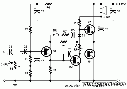
2 Watt Mini Audio Amplifier
This circuit is inexpensive, easy to assemble, and quite straightforward. It is a general audio amplifier that can be used with computers, CD players, or other devices that have a headphone output. The circuit was intentionally designed without the use...

1W guitar amplifier
An alternative to the well-known ROG Ruby amplifier, this design shares a similar topology, featuring a buffer and a chip amplifier. It employs a JFET buffer utilizing the MPF102, along with the 1W TDA7052 chip. The amplifier delivers a clean...

Simple Hybrid Audio Amplifier Circuit
Here is an amplifier circuit based on the BUZ11, which can be replaced by an IRFZ34N, and an ECC83 can be used instead of the ECC88. In this case, the anode voltage should be reduced slightly to 155 V. The...

Miniature Audio Amplifier Circuit
This miniature audio amplifier provides an output of up to 250mW and can function as a final stage audio amplifier for radio sets. The schematic is straightforward, featuring one BC transistor.
The described miniature audio amplifier is designed for efficient amplification...

tda7262 stereo 20 watts audio amplifier circuit design
The TDA7262 integrated circuit, manufactured by ST Microelectronics, can be utilized to design a straightforward stereo audio amplifier project. This circuit can deliver a maximum output power of 20 watts per channel. The TDA7262 is a dual Hi-Fi audio power...
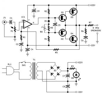
18W Audio Amplifier Circuit
Proper grounding is essential for eliminating hum and ground loops. Connect the ground terminals of J1, P1, C2, C3, and C4 to the same point. Connect C6 to the output ground. An audio amplifier is an electronic device that amplifies...

50 Watt Amplifier
This is a handy, easy to build general purpose 50 watt amp. The amp has an input for a radio, TV, stereo or other line level device. More: It also has a phono input for a record player, guitar, microphone...

25 watt audio amplifier circuit
This is a 25-watt basic power amplifier designed for ease of construction at a reasonable cost. It offers superior performance compared to standard STK module amplifiers commonly found in most mass-market stereo receivers produced today.
The 25-watt basic power amplifier circuit...