


Wideband Amplifier
#wideband amplifier
#MAR1 IC
#gain block
#Mini-Circuits Lab
#RF amplifier
#high frequency
#signal amplification

Description: This wideband amplifier utilizes a MAR1 integrated circuit (IC), functioning as a gain block. The device is produced by Mini-Circuits Lab and provides a gain of +13 dB from DC to 1000 MHz. The load resistor (Rl) is chosen to deliver a 17 mA current to the IC at +5 V. For a 12 V supply, the value is approximately 470 ohms. The RF choke (RFC1) typically ranges from 1 to 5 ohms.
The wideband amplifier design leverages the MAR1 IC, which is specifically engineered for high-frequency applications, making it suitable for RF amplification tasks. The +13 dB gain ensures that signals are amplified sufficiently across the specified frequency range, which is critical for maintaining signal integrity in communication systems.
The selection of the load resistor (Rl) is pivotal for regulating the current flowing through the IC. By providing a 17 mA current at a +5 V supply, the amplifier operates efficiently within its designed parameters, ensuring optimal performance. The choice of a 470-ohm resistor for a 12 V supply indicates the need to adjust the load to match the power supply voltage while maintaining the desired current level. This adjustment helps in stabilizing the amplifier's operation and preventing distortion of the amplified signal.
The RF choke (RFC1) plays a significant role in isolating the amplifier from power supply noise, which is crucial for maintaining the amplifier's performance, especially in high-frequency applications. The typical range of 1 to 5 ohms for RFC1 suggests that it is designed to have minimal impact on the circuit's overall impedance while effectively filtering out unwanted signals.
In summary, this wideband amplifier circuit is optimized for high-frequency applications with careful consideration of component values to ensure reliable and efficient operation across a broad frequency spectrum. This wideband amplifier uses a MAR1 IC, which is a gain block. The device is manufactured by Mini-Circuits Lab and offer s + 13-dB gain from dc to 1000 MHz. Rl is selected to provide 17-mA current to Ul at + 5 V. For 12-V supply ^ = 470 . RFC1 is typically 1 to 5 .
The wideband amplifier design leverages the MAR1 IC, which is specifically engineered for high-frequency applications, making it suitable for RF amplification tasks. The +13 dB gain ensures that signals are amplified sufficiently across the specified frequency range, which is critical for maintaining signal integrity in communication systems.
The selection of the load resistor (Rl) is pivotal for regulating the current flowing through the IC. By providing a 17 mA current at a +5 V supply, the amplifier operates efficiently within its designed parameters, ensuring optimal performance. The choice of a 470-ohm resistor for a 12 V supply indicates the need to adjust the load to match the power supply voltage while maintaining the desired current level. This adjustment helps in stabilizing the amplifier's operation and preventing distortion of the amplified signal.
The RF choke (RFC1) plays a significant role in isolating the amplifier from power supply noise, which is crucial for maintaining the amplifier's performance, especially in high-frequency applications. The typical range of 1 to 5 ohms for RFC1 suggests that it is designed to have minimal impact on the circuit's overall impedance while effectively filtering out unwanted signals.
In summary, this wideband amplifier circuit is optimized for high-frequency applications with careful consideration of component values to ensure reliable and efficient operation across a broad frequency spectrum. This wideband amplifier uses a MAR1 IC, which is a gain block. The device is manufactured by Mini-Circuits Lab and offer s + 13-dB gain from dc to 1000 MHz. Rl is selected to provide 17-mA current to Ul at + 5 V. For 12-V supply ^ = 470 . RFC1 is typically 1 to 5 .

Wideband RF Amplifier
This circuit consists of wideband RF amplifiers that utilize current-feedback components such as the THS3202. The THS3202 was selected for its fast slew rate and wide bandwidth. The amplifier voltage gain of this circuit is 20, while the stage voltage...

TV signal amplifier 470Mhz-860Mhz
This amplifier is designed to amplify RF signals from an antenna by 10 dB and operates as a Class A amplifier using the BFQ34 transistor from Philips. The BFQ34 is packaged in an SOT122A case. The BFQ34T variant is available...

1 Watt Linear RF Amplifier
The RF circuit is a C-Class power amplifier. It is used in the last stage of transmitters. Its maximum power output is about 1 Watt. The circuit can be used in 3 frequency ranges: 30-100-200 MHz. More: The P-Out column...

am rf amp for internal antenna circuit
Any NPN transistor can be used. The author used a 2N3904, but a 2N2222A should work just as well. A good, low noise transistor would be even better. Some radios only have three connections to their ferrite bar antenna: the...

600W rf power amplifier
A unique push-pull parallel circuit utilizes four MRF150 RF power FETs connected in parallel at relatively high power levels. Supply voltages ranging from 40 to 50 Vdc can be employed, contingent on the linearity requirements. The bias for each device...

5W 7Mhz Rf Power Amplifier Circuit
The circuit illustrated is designed to generate up to 5 watts of RF output in the 40-meter (7 MHz) amateur band. The coils depicted are wound on toroidal cores from Armdon Associates Inc., with part numbers provided in the schematic....

Crystal Radio RF Amplifier
The circuit presented is a straightforward yet efficient amplifier that can provide notable performance enhancements. This amplifier can demonstrate negative resistance at lower settings of the 500-ohm potentiometer, resulting in increased gain or even oscillation. Consequently, the circuit can be...
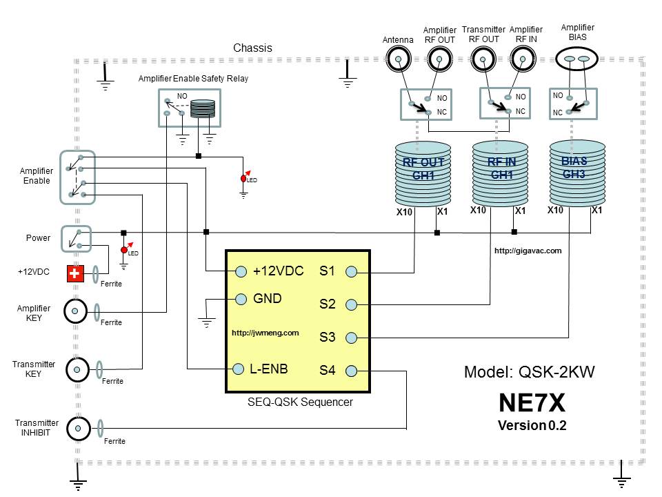
QSK 2KW
The QSK-2KW is an external RF T/R interface device that connects to any RF vacuum tube amplifier. It provides full high-speed RF amplifier T/R switching for CW or digital break-in operation. The QSK-2KW requires a low current keying input, allowing...

High frequency crystal oscillator
One section of the MC10101 is configured as a 100 MHz crystal oscillator, with the crystal placed in series within the feedback loop. An LC tank circuit is utilized to tune the 100 MHz harmonic of the crystal, which can...